Showing posts with label audio. Show all posts

Monday, September 30, 2013

AUDIO LEVEL METER ELECTRONIC DIAGRAM


AUDIO LEVEL METER ELECTRONIC DIAGRAM

It consists of only few components. IC LM3915 converts the audio analog voltage and display it to the LED. Here is the schematic :

Parts list :


  •     Resistor R1 : 1k2
  •     Resistor variable R2 : 10k
  •     IC : LM3915
  •     LED indicator LED1-LED10 : LED 5mm
  •     12V power supply


Read More...

Sunday, May 5, 2013

Reliable 6 Watt Hi Fi Audio Amplifier Using TDA2613

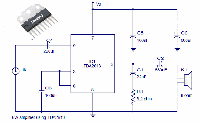
A 6 watt audio amplifier circuit using TDA2613 is shown here. TDA2613 is an integrated Hi-Fi  audio amplifier IC from Philips Semiconductors. The IC is switch ON / switch OFF click proof, short circuit proof, thermally protected and is available in 9 pin single in line plastic package. In the given circuit, TDA2613 is wired to operate from a single supply.

Capacitor C4 is the input DC decoupler while capacitors C5, C6 are power supply filters. Input audio is fed to the non inverting input through capacitor C4. Inverting input and Vp/2 pins of the IC are tied together and connected to ground through capacitor C3. Capacitor C2 couples the speaker to the ICs output and the network comprising of capacitor C1 and resistor R1 improves the high frequency stability.

Circuit diagram

6 Watt Hi Fi Audio Amplifier using TDA2613

Notes.
  • Assemble the circuit on good quality PCB.
  • Supply voltage (Vs) can be anything between 15 to 24V DC.
  • Heat sink is necessary for TDA2613.
  • Do not give more than 24V to TDA2613.
Read More...

Wednesday, April 10, 2013

25 W AUDIO AMPLIFIER MOSFET IRF530 IRF9530

25 W AUDIO AMPLIFIER MOSFET IRF530-IRF9530

The supply rails prudentially voltage was kept at the rather low value of + and - 32V.


Note:


  • Q6 & Q7 must have a small U-shaped heatsink.
  • Q8 & Q9 must be mounted on heatsink.
  • Adjust R11 to set quiescent current at 100mA (best measured with an Avo-meter connected in series to Q8 Drain) with no input signal.
  • A correct grounding is very important to eliminate hum and ground loops. Connect to the same point the ground sides of R1, R4, R9, C3 to C8. Connect C11 to output ground. Then connect separately the input and output grounds to power supply ground.


Read More...

Saturday, April 6, 2013

70 Watt MOSFET Audio Amplifier

This is use the MOSFET power amplifier circuit, amplifier circuit has a very good sound quality. With the noise is quite small, thus making the amplifier circuit is suitable for you to try. Heres the circuit.
Click to view larger.

 Power amplifier with a 70Watt power is able to issue a clear voice, and very and good loud.
Read More...

3 channel audio mixer

3 channel audio mixer is built using some of the transistor amplifier.
3 channel audio mixer circuit uses voltage 9VDC summber which can supplied from a battery. 3 channel audio mixer circuit is designed special for the purposes of this Public Amplifier.


Because the audio circuit of this mixer is designed specifically for the purpose of a portable mixer for audio public then this series has only a volume control without the tone control. Image series that looks below audio mixer is a series of mono, if you want to make a 3 channel stereo audio mixer it is necessary to make 2 pieces of a series of three channel audio mixer terebut. For more details, a series of three channel audio mixer can be seen in the following image.
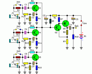
3 channel audio mixer
3 channel audio mixer circuit


Sign Component Audio Mixer With 3 Chanel Transistor
P1, P2, P3 = 5K
R1, R11, R15 = 180K
R2, R12, R16 = 2M2
R3, R13, R17 = 750R
R4, R14, R18 = 1K
R5 = 15K
R6 = 220R
R7 = 1.5K
R8 = 820R
R9 = 150R
R10 = 100K
C1, C6, C8 = 1μF-63V
C2, C4, C7, C9 = 100μF-25V
C3, C5 = 220μF-25V
Q1, Q4, Q5 = BC550C
Q2 = BC547 should
Q3 = BC557
J1, J2, J3 = 3mm Mono sockets
SW1, 2,3,4 = SPST Toggle

In a series of three channel audio mixer is equipped with a switch on each chanelnya which select the input impedance, when the switch SW1, SW2 and SW3 in the open then the input should come from the output signal with a high level such as VCD, MP3 player, tape, computer and tuner . And at SW1, SW2 and SW3 closed position, the input should come from a weak audio signals such as microphones.
Read More...

Stereo Low power audio amplifier

Stereo Low power audio amplifier
Audio amplifier circuit has a power output of 2 x 2.3 Watt, which uses IC KA2206, KA22061, LA4180, LA4182, LA4183, LA4550, LA4555, LA4558. The required voltage for at least 6 volts to 13 volts DC maximum. Component takes is a ic that I mentioned above one of them, and several capacitors elco.


This Schematics low power amplifier

schematics LA4558

Component Description
C1 = 1uF
C2 = 100uF
C3 = 100uF
C4 = 100uF
C5 = 0.1uF
C6 = 470uF
C7 = 1uF
C8 = 100uF
C9 = 100uF
C10 = 100uF
C11 = 0.1uF
C12 = 470uF
ICs can use the ic which I mention above for each ic datasheet can be seen itself.
Read More...