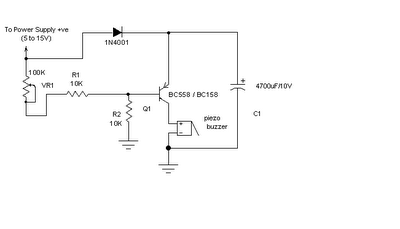
LM723 Variable Power Supply Circuit diagram
Saturday, January 11, 2014
Variable Power Supply Using LM723
LM723 Variable Power Supply Circuit diagram
Friday, January 10, 2014
High Current Power Supply
Since my page was first posted, I have received a number of emails asking about a high current power supply. I looked around, but couldnt find one that was suitable. So, I designed this. It is a linear supply, which might have a few of you rolling your eyes, but it takes very few parts, is simple to build and can supply huge currents
High Current Power Supply Circuit diagram :
Parts Table :
| Part | Total Qty | Description |
| R1 | 1 | 680 Ohm 1/4 Watt Resistor |
| C1 | 1 | 20,000 - 50,000uF 20-40 Volt Capacitor |
| C2, C3 | 2 | 100uF 50 Volt Capacitor |
| C4 | 1 | 0.1uF 50 Volt Capacitor |
| C5 | 1 | 0.01uF 50 Volt Capacitor |
| D1 | 1 | Zener Diode (See Notes) |
| Q1 | 1 | 2N3055 Or Other (See Notes) |
| T1 | 1 | Transformer (See Notes) |
| BR1 | 1 | Bridge Rectifier (See Notes) |
| S1 | 1 | SPST 250 VAC 10 A Switch |
| MISC | 1 | Case, Line Cord, Heatsink For Q1, Binding Posts For Output |
Notes :
- D1 should be rated at about one volt higher than then desired output of the supply. A half watt diode will do.
- Q1 can be a transistor similar to the 2N3055. I chose the 2N3055 for its availability and power handling (150 watts).
- T1 should be about 5 volts higher than the desired output of the supply, and rated for about one amp more of current. The voltage overhead is required by the regulator section. The extra current is to keep the transformer from over heating.
- The choice of BR1 will depend on the voltage and current of your transformer. The rectifier should be rated for 50 volts more than the transformer, and 5 amps more than the transformer.
- The value of R1 will be smaller when supplying high currents. Expiriment until you get what you need.
- Heatsink and fans are absolutely necessary!
Sunday, October 6, 2013
3V DC to 5V DC REGULATED POWER SUPPLY ELECTRONIC DIAGRAM
A 5V DC regulated output from 2 cells 3V DC batteries. The output current of the circuit is limited to 50mA. However, it still able to supply many microcontroller circuits. 3009 and 560R Resistor provide the 5V DC output, make up a voltage divider network.
Monday, May 27, 2013
Add this Short Circuit Protection to Your Power Supply
The biggest enemy of all power supply units is a possible short circuit that might occur at its output terminals due to an accidental connection or due to the fault with the connected load.
There are various electronic circuits that might be employed with a power supply unit for checking this problem, however these circuits sometimes themselves are at risk of getting damaged due to the limitations with many electrical parameters.
A very innovative way of rectifying this problem has been shown in this article. A single relay is used for sensing as well as tripping the output from the involved malfunction.
Referring the circuit diagram, we see that a relay is connected directly to the output of the power supply DC output, however the connection is made through the N/O contacts of the relay. These contacts are also terminated as the output of the unit.
N/O means normally open, that means the contacts are open initially, which in turn keeps the output disconnected from the positive of the power supply.
Now when the shown push button is momentarily pushed, the N/O contacts are bypassed allowing the current to flow across the relay coil.
The relay coil energizes, closing the N/O contacts, which in turn latches and sticks to the position even after the push button is released.
The relay latch maintains this latched position as long as the output is used under normal conditions, but when a short is made or happens across the output terminals of the supply, voltage drops rapidly across the relay coil and it immediately trips, cutting OFF the supply to the output and in the course switches OFF the latch preventing the short hazard conditions.

Tuesday, May 14, 2013
Power on time delay circuit
This circuit is time delay circuit to power on.Most of electrical equipments burn due to power failures so this circuit is a best answer for that.
Note
# This circuit operates with 12V power supply
Saturday, April 13, 2013
Automatic AC Power Switch
Thursday, April 11, 2013
4 X 15 Watt Mini Power Amplifier
4 X 15 Watt Mini Power Amplifier Circuit diagram :
The internal preamplifier’s ground pin (pin5) is connected to the common ground through a 10 Ohm resistor which makes the input ground separated from the common ground by a resistance of 10 ohms and this improves the noise rejection. The 100uF capacitor works as a power supply de-coupler. The resistor networks connected to the output lines of each amplifier improves the high frequency stability. The variable resistors (R3, R4, R12 and R13) works as the volume controller for the corresponding channels.
Notes :
- Assembling the circuit on a good quality PCB is a must for obtaining optimum sound quality.
- Use 12V DC for powering the circuit.
- The ICs must be fitted with adequately sized heat sinks.
- R3, R4, R12 and R13 serves as volume controllers.
- K1 to K4 can be 4 Ohm, 20W speakers.
- This amplifier circuit can be used in a variety of applications such as car audio systems, home theater systems, personal audio systems, public address systems etc.
Wednesday, April 10, 2013
1957 58 Dodge 4 Way Power Seat Wiring Diagram
![]() |
| 1957-58 Dodge 4-Way Power Seat Wiring Diagram |
Power Supply Failure Alarm
![]() |
| Power Supply Failure Alarm Circuit |
Tuesday, April 9, 2013
Low Cost Dual Power Supply
Circuit diagram:

The theoretical plus and minus output tracking ability is 100% since the device will provide an output voltage at one-half of the instantaneous supply voltage in the absence of a capacitor on the bypass terminal. The actual error in tracking will be directly proportional to the unbalance in the quiescent output voltage. An optional 1MO potentiometer may be installed with its wiper connected to pin 1 of the LM380 IC to null any output offset. The unbalanced current output is limited by the power dissipation of the package.
In the case of sustained unbalanced excess loads, the device will go into thermal limiting as the internal temperature sensing circuit begins to function. And for instantaneous high current loads or short circuits, the device limits the output current to approximately 1.3A until thermal shutdown takes over or the fault is removed. For maximum output power (2.5W), all ground pins (3-5 & 10-12) should be soldered to a large copper area (the LM380 data sheet contains more details).
Adjustable Stabilized Power Supply 0 15V 5A
Adjustable Stabilized Power Supply 0-15V / 5Aadapted ability accumulation can be adapted amid a few volts and 15V
with P1 and with P2 acclimatize the high absolute ( 15.0V ). R6 amount
is 0.7V / Imax area Imax is the best current. At Imax = 5A, R6 is
0.14Ω
heatsinks because ability losses are abundant at a low achievement
voltage and a Imax according accepted but you can affix the lamp L to
abate this losses.
this adjustable ability accumulation and works great! I achievement
you’ll adore it too and accept fun body this abundant counterbalanced
ability supply.
Monday, April 8, 2013
5 to 15V Regulated Power Supply Rise
Computer Power Supply for Battery Charger
Some workbenches can’t help ending up looking like a rats nest of cables and equipment, so its always an advantage if a piece of mains equipment can be removed from somewhere to free up an extra mains socket. Here we are using the ubiquitous PC as a battery charger. An unused serial interface port can supply enough current to charge (or trickle charge) low-capacity Nickel Cadmium (NiCd) batteries. You could for example, use the batteries in a radio and charge them during use.
The three serial port connections TxD, DTR, and RTS, when not in use, are at –10 V and can supply a current of around 10 to 20mA (they are short-circuit protected). The circuit shown supplies a charging current of approximately 30mA. If it is necessary to alter the polarity of the charging circuit then it is a simple job to reverse the diodes and using software, switch the port signals +10 V. Those interested could also write a software routine to automatically recharge the batteries.
Source : www.extremecircuits.net
Sunday, April 7, 2013
25W Hi Fi Power Amplifier Circuit

The supply voltage should be a maximum of ±25V. This supply is easily obtained from a 20-0-20V transformer. All resistors should be 1/4W or 1/2W 1% metal film for lowest noise, with the exception of R9, R10 and R15 which should be 1/2W types, and R13, R14 must be 5W wire wound. The bootstrap capacitor (C5) needs to be rated at least 25V, but the other electrolyc can be any voltage you have available. The potentiometer (VR1) must be a multi turn type, as the current setting is critical. Each of these amps will require a 0.25°C/W heat sink (very large). Consider using a fan or even water cooling to keep temperatures as low as possible.
Saturday, April 6, 2013
Stereo Low power audio amplifier


C1 = 1uF
C2 = 100uF
C3 = 100uF
C4 = 100uF
C5 = 0.1uF
C6 = 470uF
C8 = 100uF
C10 = 100uF
C12 = 470uF
Friday, April 5, 2013
Low Power FM Transmitter Schematic
Because the trimmer cap is very sensitive, make the final frequency adjustment on the receiver. When assembling the circuit, make sure the rotor of C3 is connected to the +9V supply. This ensures that there will be minimal frequency disturbance when the screwdriver touches the adjustment shaft. You can use a small piece of non copper-clad circuit board to make a screwdriver - this will not alter the frequency.
The frequency stability is improved considerably by adding a capacitor from the base of Q1 to ground. This ensures that the transistor operates in true common base at RF. A value of 1nF (ceramic) as shown is suitable, and will also limit the HF response to 15 kHz - this is a benefit for a simple circuit like this, and even commercial FM is usually limited to a 15kHz bandwidth.
The Principle of works this application;
Q1 is the oscillator, and is a conventional design. L1 and C3 (in parallel with C2) tune the circuit to the desired frequency, and the output (from the emitter of Q1) is fed to the buffer and amplifier Q2. This isolates the antenna from the oscillator giving much better frequency stability, as well as providing considerable extra gain. L2 and C6 form a tuned collector load, and C7 helps to further isolate the circuit from the antenna, as well as preventing any possibility of short circuits should the antenna contact the grounded metal case that would normally be used for the complete transmitter.
The audio signal applied to the base of Q1 causes the frequency to change, as the transistors collector current is modulated by the audio. This provides the frequency modulation (FM) that can be received on any standard FM band receiver. The audio input must be kept to a maximum of about 100mV, although this will vary somewhat from one unit to the next. Higher levels will cause the deviation (the maximum frequency shift) to exceed the limits in the receiver - usually ±75kHz.
With the value shown for C1, this limits the lower frequency response to about 50Hz (based only on R1, which is somewhat pessimistic) - if you need to go lower than this, then use a 1uF cap instead, which will allow a response down to at least 15Hz. C1 may be polyester or mylar, or a 1uF electrolytic may be used, either bipolar or polarise. If polarised, the positive terminal must connect to the 10k resistor.
Tuesday, April 2, 2013
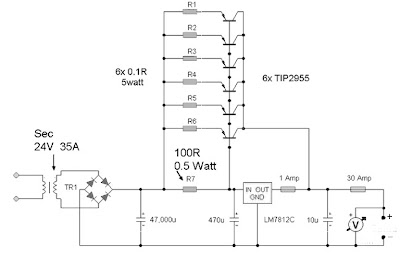
35 Ampere Power Supply

Series Power Supply 12Volt 35 Amp uses 6 units TIP2955 type power regulator transistors. I use a type MJ2955 TIP2955 not because packaging TIP2955 easier to install heatsink. The series 12Volt 35 Amp Power Supply can be loaded up to 35A depending on the travo which we attach. The series 12Volt 35 Amp Power Supply is very simple, because the voltage regulators make use of IC7812 which will leave a power regulator alone. For more details, series 12Volt 35 Amp Power Supply can be seen in thethe following figure .
![]() |
| 12Volt 35Ampere schematic |