Showing posts with label switch. Show all posts

Tuesday, October 8, 2013

Automatic Switch For Voltage Converters

New applications for DC voltage converters, such as the ‘workhorse’ LT1070, arise every day. These converters can be adapted to nearly every imaginable ratio of input and output voltages. However, all of these circuits and devices have the same shortcoming, which is that they lack an on/off switch. Especially when they are used as a source of 6-V / 12-V power for a car radio, this is highly impractical. The circuit described here adds automatic load detection to the converter. For use in a car, the additional circuitry must be small and fit into a compact enclosure together with the converter.

Since the battery voltage and ambient temperature vary over wide ranges, a simple form of load detection must be used. Besides this, the voltage drop across the load sensing circuitry must naturally be as small as possible. This can be achieved by using ‘ultra-modern’ SiGe technology. The 6 V from the battery and the 12 V from the converter are combined in the MB R2545 dual diode. Consequently, a voltage of at least 6 V is always applied to the radio (for memory retention). If the radio is switched on, it draws a current from the 6-V battery, which may be around 100 mA.

This current produces a voltage across R1. If this voltage is 75 mV or greater, the AC128 germanium transistor starts conducting and charges electrolytic capacitor C1, which is connected to the gate of the BUZ10. The MOSFET energises RE1 and thus connects the supply voltage to the converter. As a result, 12-V power is connected to the radio. The resulting increased current causes the voltage drop across R1 to increase, which is undesirable, so a 10-A Schottky diode is connected in parallel. The total voltage drop is thus approximately 0.6 V. The RC network connected to the BUZ10 ensures that the transistor always remains switched on for at least several seconds, to prevent the circuit from ‘chattering’ with varying current consumption.

Automatic Switch Circuit Diagram For Voltage Converters
If the load is switched off, the AC128 cuts off, the electrolytic capacitor discharges and the relay again disconnects the voltage converter. The residual current consumption is so small that the circuit can also be connected ahead of the ignition switch. The Schottky diodes need only be rated for the necessary voltages and currents, and above all, they should have the lowest possible saturation voltage. The exact type is not critical. Two separate diodes can also be used. A small heat sink for the MBR diode won’t hurt, but this is normally not essential. Practically any type of PNP germanium transistor that is still available or on hand can be used (AC125, AC126 and AC128 work perfectly).

It may be necessary to modify the value of R1. In combination with the germanium transistor, R1 determines which level of current will be ignored (for memory retention) and which level of current will cause the converter to be switched on. With the component values shown in Figure 1, this level is between 10 mA and 25 mA. It is recommended to measure the quiescent current (at 6 V) and switch-on current of the load and then simulate the switching process using dummy load resistors. When selecting the 6-V relay, ensure that its contacts have an adequate current rating. The actual value can be significantly greater than the nominal output current. With a load of 5 A at 12 V and a converter efficiency of 70 percent, the current through the relay contacts rises to 14.3 A.
Read More...

Thursday, September 26, 2013

Electronic Touch Switch

Mechanical contacts have the disadvantage that they wear out. That is why it is practical to use an electronic ‘touch switch’ in some situations. With such a touch switch the resistance of the human skin is used for the switching action. The schematic shows the design of a circuit that senses the resistance of the skin and converts it into a useful switching signal. The touch switch contacts can be made from two small metal plates, rivets, nails, etcetera, which are placed close together on a non-conducting surface. In this circuit a comparator of the type LM393 has been used. In the idle state there is, via R1, a voltage equal to the power supply voltage on the non-inverting input of IC1a. Because the inverting input of IC1a is set with R2 and D3 to D5 at the supply voltage minus 1.8 V, the open-collector output of IC1.a is, via R3, equal to the power supply voltage. This voltage is inverted by IC1.b. The voltage at the non-inverting input of IC1.b amounts to half the power supply voltage (through voltage divider R4 and R5) and is lower than the voltage on the inverting input.

Circuit diagram:

electronic-touch-switch-circuit-diagramw

Electronic Touch Switch Circuit Diagram

The output of IC1.b is therefore a ‘0’. If the two touch contacts are bridged with a finger, the voltage at the non-inverting input will become low enough to cause the comparator to toggle state. The moistness of the skin results in a resistance of 1 to 10 MR. If this circuit is used in the vicinity of equipment that’s connected to the mains, then it can be sufficient to touch only the upper contact to operate the switch, provided that the circuit has been earthed. The body then acts as an antenna which receives the 50 Hz (or 60 Hz) from the mains. This is enough to toggle IC1.a at the same 50 Hz. C1/R3 prevent this 50 Hz from reaching the input of IC1b and provide a useable ‘pulse’ of about 10 s at the output of IC1.b. Note that a fly walking across the touch switch conducts enough to generate a switching signal. So do not operate important things with this circuit (such as the heating system or the garage door). Do not make the wires between the touch contacts and the circuit too long to prevent picking up interference. The power supply voltage for the circuit is not very critical. Any regulated DC voltage in the range from 6 to 20 V can be used.

Author: Heino Peters - Copyright: Elektor Electronics Magazine

Read More...

Tuesday, June 4, 2013

Switch Wiring Diagram Variationelectrical Online

Electrical Wiring on Jeep Grand Cherokee Radio Adaptor Wiring Harness   Circuit Schematic
Jeep Grand Cherokee Radio Adaptor Wiring Harness Circuit Schematic.


Electrical Wiring on Way Switch Wiring Diagram Variation  3   Electrical Online
Way Switch Wiring Diagram Variation 3 Electrical Online.


Electrical Wiring on 250 And 525 Sx  Mxc  Exc Electrical System And Wiring Diagram Here
250 And 525 Sx Mxc Exc Electrical System And Wiring Diagram Here.


Electrical Wiring on Installing Home Electrical Wiring For Breakers And Fuses Inside A
Installing Home Electrical Wiring For Breakers And Fuses Inside A.


Electrical Wiring on Electrical Wiring In The Home  Wires Are Not Hot In Electrical Outlet
Electrical Wiring In The Home Wires Are Not Hot In Electrical Outlet.


Electrical Wiring on Auto Electrical Wiring Diagram Manual   Circuit Schematic
Auto Electrical Wiring Diagram Manual Circuit Schematic.


Electrical Wiring on Diagram Electrical Wiring
Diagram Electrical Wiring.


Electrical Wiring on Wiring Is Done In Parallel Garbage Disposal Wiring Fuses And Breakers
Wiring Is Done In Parallel Garbage Disposal Wiring Fuses And Breakers.


Electrical Wiring on Randy S Electric  Wiring For Your Home Renovation Projects
Randy S Electric Wiring For Your Home Renovation Projects.


Electrical Wiring on Series 600 Electric Wiring Diagram   Car Parts And Wiring Diagram
Series 600 Electric Wiring Diagram Car Parts And Wiring Diagram.


Read More...

Thursday, May 30, 2013

Light Outlet Switch Wiring Diagram

Wiring Diagrams on The Following Schematic Shows A Typical Diagram Schematic Of Polaris
The Following Schematic Shows A Typical Diagram Schematic Of Polaris.


Wiring Diagrams on Schematic Diagram
Schematic Diagram.


Wiring Diagrams on Installing A Tachometer In Your Ford Ranger
Installing A Tachometer In Your Ford Ranger.


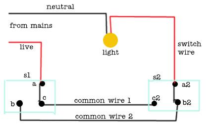
Wiring Diagrams on Light With Outlet 2 Way Switch Wiring Diagram
Light With Outlet 2 Way Switch Wiring Diagram.


Wiring Diagrams on In Pairs Above Is A Simple Schematic Diagram Of How The Wiring For
In Pairs Above Is A Simple Schematic Diagram Of How The Wiring For.


Wiring Diagrams on Power At Light 4 Way Switch Wiring Diagram
Power At Light 4 Way Switch Wiring Diagram.


Wiring Diagrams on Basic 2 Way Switch Wiring Diagram
Basic 2 Way Switch Wiring Diagram.


Wiring Diagrams on Post It But I Ll Try To Diagram It Here
Post It But I Ll Try To Diagram It Here.


Wiring Diagrams on Dodge Dakota Radio Wiring Diagram 1998 Dodge Ram 1500 Wiring Diagram
Dodge Dakota Radio Wiring Diagram 1998 Dodge Ram 1500 Wiring Diagram.


Wiring Diagrams on Wiring Diagram For Manual Service   Motorcycle Diagrams Collection
Wiring Diagram For Manual Service Motorcycle Diagrams Collection.


Read More...

Wednesday, May 1, 2013

Simple Light Switch

This is a light switch or light activated relay circuit.The relay on when LDR uncoverd and relay off when LDR covered.Adjust VR1 for light sensitive.LED will turn on at the same time with relay
Read More...

Saturday, April 13, 2013

Automatic AC Power Switch

Electrical appliances accidentally left on  in (holiday) homes left unoccupied for a  brief or a protracted length devour power  unnecessarily and may existing a fire hazard. Everyone shall be accustomed to those  nagging thoughts, a quantity of miles down the  highway from the home: “Did I remember  to change off the espresso machine? The  milds? The oven?” 

Circuit diagram :
Automatic AC Power Switch Circuit Diagram

Hotel rooms are regularly equipped with a  swap near the main door which allows the facility supply to the entire thing in  the room simplest when the plastic card (which  may contain a chip or have a magnetic strip  or a sample of holes) that serves because the room  secret's inserted. The circuit thought given here  to modify off gentles and different home equipment is  alongside the identical lines. The answer is distinctly easy. 

A reed contact is suited for the body of the main entrance door, and a matching magnet  is hooked up to the door itself such that when  the door is closed the reed contact is also  closed. To allow power to the house, press  S1 briefly. Relay RE1 will pull in and complete  the circuit for all of the AC powered home equipment in  the house. The relay will be held in even after  the button is liberated by means of the second relay contact and the reed contact (‘latching’ function). 

As quickly as the primary entrance door is  opened, the reed contact may even open.  This in flip releases the latch circuit and  consequently the relay drops out. The  various linked home equipment will thus  routinely and that inevitably be switched  off as quickly as the house is left. The circuit is mainly designed for  small vacation properties, where this mode  of operation is especially sensible. Of course, for any circuit that deals in AC  powerline voltages, we should mention  the next caution. 

Caution:
shock hazard! Construction and connection of this circuit  will have to simplest be carried out by suitably-qualified  personnel, and all applicable electrical safety  rules must be observed. In particular, it  is essential to be positive that the relay chosen is  acceptable to be used at domestic AC grid volt-ages and is suitably rated to hold the required  current.


http://www.ecircuitslab.com/2012/04/automatic-ac-power-switch.html
Read More...

Friday, April 12, 2013

Triac Light Switch as a dimers

The series of light switches this time slightly different from the voltage of work. The series of light switches can work directly on the AC power network. Light switches are using the main component of TRIAC and LDR. The circuit is very simple and the components were sold in the market.

If you want a light reception sensitivity of this circuit can be arranged then the 3.3 MOhm resistor can be replaced with a variable resistor. For more details can be seen from the following series of images.
Circuit Diagram

With Triac Light Switch series is as dimers, but dimers control performed by the reception of light around the LDR. The lower the intensity cayaha received LDR then  bright lights. For installation LDR need to be considered so as not exposed to light from the lamp directly.
Read More...

Dew Sensitive Switch Circuit Using LM358

This is a simple design circuit that can be used to switch ON or OFF a device when the dew present in the surrounding atmosphere crosses a set value. This circuit uses a dew sensitive resistive element and a comparator based on LM 358 to perform the above said operation. This is the figure of the circuit.


In operation of the circuit, at normal condition the resistance of dew sensor element will be low and so the voltage drop across it. So the voltage at the non inverting pin of LM358 (IC1) will be less than the voltage at the inverting input of the LM358.So the output of the op amp will be low. This keeps the opto coupler (MCT2E) deactivated. When the dew increases the resistance of the element increases and so do the voltage across it. Now the voltage at the non inverting pin of LM358 (IC1) will be higher than the voltage at the inverting input of the LM358.So the output of the op amp will be switched to high. This in turn activates the opto coupler. The LED glows to indicate it. As a result we get an opto coupler activated and de activated according to the amount of dew in the atmosphere. The output pins of opto coupler pin (5&4) can be used to control the external device.

Diode D1, resistors R6&R3 and capacitor C1 is employed here to derive the power for the circuit directly from mains. The dew sensor is hard to find in market. But it can be easily obtained from a old VCR. Also the type no of the sensor is not so important here. Try with any thing you get. I used one from a old Hitachi VCR. LM 358 is a dual op amp. Here only one op amp inside it is used.


Read More...

Thursday, April 11, 2013

USB Switch Schematic Circuit

Anyone experimenting or developing USB ported peripheral hardware soon be comes irritated by the need to disconnect and connect the plug  in order to reestablish communication with the PC. This process is necessary for example each time the peripheral equipment is reset or a new version of the firmware is installed. As well as tiresome it eventually leads to excessive contact wear in the USB connector. The answer is to build this electronic isolator which disconnects the peripheral device at the touch of a button. This is guaranteed to reduce any physical wear and tear and restore calm once again to the workplace. 

Circuit image :
 USB Switch-Image
USB Switch Schematic Circuit Image

The circuit uses a quad analogue switch type 74HC4066. Two of the switches in the package are used to isolate the data path. The remaining two are used in a classic bistable flip-flop configuration which is normally built using transistors. A power MOSFET switches the power supply current to the USB device.  Capacitor C2 ensures that the flip flop always  powers-up in a defined state when plugged  into the USB socket (‘B’ in the diagram). 

The  peripheral device connected to USB socket ‘A’  will therefore always be ‘not connected’ until  pushbutton S2 is pressed. This flips the bistable, turning on both analogue gates in the data lines and switching the MOSFET on. The  PC now recognises the USB device. Pressing  S1 disconnects the device.
Circuit diagram :
USB Switch-Circuit-daigram
USB Switch Schematic Circuit Diagram

The circuit does not sequence the connections as a physical USB connector does; the power supply connection strips are slightly longer than the two inner data carrying strips to ensure the peripheral receives power before the data signals are connected. The electronic switch does not suffer from the same contact problems as the physical  connector so these measures are not required in the circuit. The  simple circuit can quite easily be constructed on a small  square of perforated strip-board. 

The design uses the 74HC(T)4066 type analogue switch, these have  better characteristics compared to the standard 4066 device. The USB switch is suitable for both low-speed (1.5 MBit/ s) and full-speed (12 MBit/s) USB ports applications but the proper ties of the analogue switches and perf-board construction  will not support hi-speed (480 MBit/s) USB operation. 

The IRFD9024 MOSFET can pass a current of  up to 500 mA to the peripheral device with-out any problem.
 
 
 http://streampowers.blogspot.com/2012/07/touch-switchs.html
Read More...

Monday, April 8, 2013

Remote controlled appliance switch circuit

Description.
Here is a versatile remote controlled appliance switch that can ON or OFF any appliance connected to it using a TV remote.

 IR remote sensor IC TSOP 1738 is used for recieving the signal.
Normally when no signal is falling on IC3 the output of it will be
high.This makes Q1 OFF.When a signal of 38 KHz from the TV remote falls
on the IC3 its output goes low.This makes Q1 conduct and a negative
pulse is obtained at pin 2 of IC 1  NE 555.Due to this IC1 wired as a
monostable multivibrator produces a 4 Sec  long high signal at its out
put.This high out put is the clock for IC 2 which is wired as a Flipflop
and of , its two outputs pin 3 goes low and pin 2 goes high.The high
output at pin 2 is amplified to drive the relay .For the next signal 
the outputs of IC2 toggles state. Result, we get a relay toggling on
each press on the remote.Any appliance connected to this circuit can be
switched ON or OFF.
Circuit Diagram with Parts List .
Notes.
  • Before
    wiring the circuit make sure that the carrier frequency  of the TV
    remote you have is 38 KHz.For that wire the sensor part only ,point
    your remote to the TSOP1738 and press any switch.If  out put of
    TSOP1738  goes  low them ok, your remote is of 38Khz type.Nothing to
    worry almost all TV remote are of this type.
  • You can use any
    switch because for any switch the code only changes,the carrier
    frequency remains same.We need this carrier frequency only.
  • Assemble the circuit on a good quality PCB or common board.
  • The appliance can be connected through NO or NC  and contacts of the relay .

Read More...

Saturday, April 6, 2013

Keyboard Mouse Switch Unit

Unplugging or re-connecting equipment to the serial COM or PS2 connector always gives problems if the PC is running. Even if you only need to swap a mouse or changeover from a graphics keyboard to a standard keyboard. The chances are that the connected equipment will not communicate with the PC, it will always be necessary to re-boot. If you are really unlucky you may have damaged the PC or the peripheral device. In order to switch equipment successfully it is necessary to follow a sequence. The clock and data lines need to be disconnected from the device before the power line is removed. And likewise the power line must be connected first to the new device before the clock and data lines are re-connected.

This sequence is also used by the USB connector but achieved rather more simply by using different length pins in the connector. The circuit shown here in Figure 1 performs the switching sequence electronically. The clock and data lines from the PC are connected via the N.C. contacts of relay RE2 through the bistable relay RE1 to connector K3. Pressing push-button S1 will activate relay RE2 thereby disconnecting the data and clock lines also while S1 is held down the semiconductor switch IC1B will be opened, allowing the voltage on C4 to charge up through R4. After approximately 0.2 s the voltage level on C4 will be high enough to switch on IC1A, this in turn will switch on T1 energizing one of the coils of the bistable relay RE1 and routing the clock, data and power to connector K2.


When S1 is released relay RE2 will switch the data and clock lines through to the PC via connector K1. It should be noted that the push-button must be pressed for about 0.5s otherwise the circuit will not operate correctly. Switching back over to connector K3 is achieved similarly by pressing S2. The current required to switch the relays is relatively large for the serial interface to cope with so the energy necessary is stored in two relatively large capacitors (C2 and C3) and these are charged through resistors R1 and R6 respectively. The disadvantage is that the circuit needs approximately 0.5 minute between switch-overs to ensure these capacitors have sufficient charge.

The current consumption of the entire circuit however is reduced to just a few milliamps. The PCB is designed to accept PS2 style connectors but if you are using an older PC that needs 9 pin sub D connectors then these will need to be connected to the PCB via flying leads. In this case the mouse driver software configures pin 9 as the clock, pin 1 as the data, pin 8 (CTS) as the voltage supply pin and pin 5 as earth.

Resistors:
R1 = 2kΩ2
R2 = 47kΩ
R3 = 10kΩ
R4 = 4kΩ7
R5 = 1kΩ
R6 = 1kΩ2
Capacitors:
C1 = 10µF 10V radial
C2 = 1000µF 10V radial
C3 = 2200µF 10V radial
C4 = 2µF2 10V radial
Semiconductors:
D1-D5 = 1N4148
T1 = BC547
IC1 = 4066 or 74HCT4066
Miscellaneous:
RE1 = bistable relay 4 c/o contacts
RE2 = monostable relay 2 c/o contacts
K1,K2,K3 = 6-way Mini-DIN socket (pins at 240°, PCB mount
S1,S2 = push-button (ITTD6-R)
Read More...