Showing posts with label circuit. Show all posts

Friday, January 10, 2014

Build a Room Ioniser Circuit Diagram

This is a voltage multiplier circuit acting as an Room Ioniser Circuit Diagram. Its calculated to feed 220V from mains and the output is about 6KV. Caution should take with the circuit as can be dangerous due to mains. You can place a needle at the output 3cm long. Even you disconnect from mains, capacitors can be dangerous so make sure to discharge them by shorting their pins before you touch the circuit with hands.

Room Ioniser Circuit Diagram

Build a Room Ioniser Circuit Diagram
 
Read More...

Wednesday, December 18, 2013

Step up Down DC DC Converter Circuit Diagram

Positive output step-up and step-down dc-dc converters have a common limitation in that neither can handle input voltages that are both greater than or less than the output. For example, when converting a 12-V sealed lead/acid battery to a regulated +12 V output, the battery voltage might vary from a high of 15 V down to 10 V. 

By using a MAX641 to drive separate P-and N-cbannel MOSFETs, both ends of the inductor are switched to allow noninverting buck/boost operation. A second advantage of the circuit over most boostonly designs is that the output goes to 0 V when shutdown is activated. Inefficiency is a drawback because two MOSFETs and two diodes increase the losses in the charge and discharge path of the inductor. The circuit delivers +12 V at 100 mA at 70 percent efficiency with an 8-V input.


Step up Down DC - DC Converter Circuit Diagram

Step up Down DC - DC Converter Circuit Diagram

Read More...

Sunday, September 1, 2013

Simple Short Wave Transmitter Circuit

Description 
This low-cost short-wave transmitter is tunable from 10 to 15 MHz with the help of ½J gang condenser VC1, which determines the carrier frequency of the transmitter in conjunction with inductor L1. The frequency trimming can be done with VC2. The carrier is amplified by transistor T4 and coupled to RF amplifier transistor T1 (BD677) through transformer X1*. The transmitter does not use any modulator transformer.
The audio output from condenser MIC is preamplified by transistor T3 (BC548). The audio output from T3 is further amplified by transistor T2 (BD139), which modulates the RF amplifier built around transistor T1 by varying the current through it in accordance with the audio signal’s amplitude. RFC1 is used to block the carrier RF signal from transistor T2 and the power supply. The modulated RF is coupled to the antenna via capacitor C9.
Circuit Diagram:
 For antenna, one can use a 0.5m long telescopic aerial. Details of RF choke, inductor L1 and coupling RFC1 is used to block the carrier RF signal from transistor T2 and the power supply. The modulated RF is coupled to the antenna via capacitor C9. For antenna, one can use a 0.5m long telescopic aerial. Details of RF choke, inductor L1 and coupling transformer X1, we used a ready made short-wave antenna coil with tuning slug (Jawahar make), which worked satisfactorily. We tested the transmitter reception up to 75 metres and found good signal strength.

Read More...

Wednesday, June 12, 2013

FM Transmitter Circuit

Nothing critical here. To get a bit of tuning out of the coil you could put a 4-40pF trimmer capacitor (optional) parallel over the 1 μH coil, L1. C1/C4 and C5/C6 are ceramic capacitors, preferably NPO (low noise) types. C2/C3 are electrolytic or can be tantalum types. The antenna is nothing more than a piece of 12" wire or a piece of piano wire from 6" to 12".

To find the signal on your receiver, make sure there is a signal coming into the microphone, otherwise the circuit wont work. I use an old mechanical alarm clock (you know, with those two large bells on it). I put this clock by the microphone which picks up the loud tick-tock. Im sure you get the idea... Or you can just lightly tap the microphone while searching for the location of the signal on your receiver.

Parts List

R1,R3 = 100K
R2 = 10K
R4 = 470 ohm
C1,C4 = 470pF
C2,C3 = 4.7μF, 16V, electrolytic
C5,C6 = 4.7pF
C7 = 4-40pF trimmer cap (optional, see text)
L1 = 1μH
Q1,Q2 = 2N2222, NPN transistor
Mic = Electret Microphone
B1 = 9 Volt, Alkaline battery
Read More...

Wednesday, June 5, 2013

Residential Circuit Diagram Electrical Wiring Information

Electrical Wiring Diagrams on Residential Circuit Diagram Electrical Wiring Information
Residential Circuit Diagram Electrical Wiring Information.


Electrical Wiring Diagrams on 1964 Gmc Truck Electrical System Wiring Diagram   Circuit Schematic
1964 Gmc Truck Electrical System Wiring Diagram Circuit Schematic.


Electrical Wiring Diagrams on Honda Goldwing Gl1100 Wiring Diagram And Electrical System Harness
Honda Goldwing Gl1100 Wiring Diagram And Electrical System Harness.


Electrical Wiring Diagrams on Typical 7 Way Trailer Wiring Diagram   Circuit Schematic
Typical 7 Way Trailer Wiring Diagram Circuit Schematic.


Electrical Wiring Diagrams on Standard Electric Water Heater Operation
Standard Electric Water Heater Operation.


Electrical Wiring Diagrams on Three Way Switch Wiring Diagram
Three Way Switch Wiring Diagram.


Electrical Wiring Diagrams on Diagram Electrical Wiring
Diagram Electrical Wiring.


Electrical Wiring Diagrams on Typical Ac Panel Wiring Diagram
Typical Ac Panel Wiring Diagram.


Electrical Wiring Diagrams on Installing Home Electrical Wiring For Breakers And Fuses Inside A
Installing Home Electrical Wiring For Breakers And Fuses Inside A.


Electrical Wiring Diagrams on Wiring Diagram Electric Mirror Wiring Diagram Peugeot 307 Abs Wiring
Wiring Diagram Electric Mirror Wiring Diagram Peugeot 307 Abs Wiring.


Read More...

Wednesday, May 29, 2013

Long range AM transmitter Circuit

This is a long range transmitter.This circuit can send signals up to 2km.So that you have to use 1m copper wire.The power of this transmitter has been increased by usin two transistors. When you use this transmitter do give power with out connecting the antenna.Because it will burn your transistors.


Note
# The transformer T1 can be a general purpose audio driver transformer seen in transistor radios.

# The inductor L1 can be made by making 56 turns of 365 WG enameled copper wire on a 1 cm former.

# Inductor L2 can be a 10 mH general purpose radio frequency choke.

# The circuit can be powered from a 9V PP3 battery.
Read More...

Simple Circuit Temperature Controlled DC Fan

Simple Circuit Temperature Controlled DC FanHere is a Simple Circuit Temperature Controlled DC Fan primarily based on 2 transistors which will be used to control the speed of a 12 V DC fan looking on the temperature.A thermistor (R1) is employed to sense the temperature. When the temperature will increase the base current of Q1 (BC 547) will increase that in flip decreases the collector voltage of the same transistor. Since the collector of Q1 is coupled to the base of Q2 (BD 140), the decrease in collector voltage of Q1 forward biases the Q2 lot of and so do the speed of the motor. Also, the brightness of the LED are going to be proportional to the speed of the motor.

Notes.

  • The R1 can be a 15K @ 20°C ,N.T.C thermistor.
  • The M1 can be a 12V,700mA fan motor.
  • The capacitor C1 must be rated 25V.
  • The circuit can be powered from a 12V PP3 battery or 12V DC power supply.
  • Assemble the circuit on a good quality PCB or common board.
Read More...

Simple Electro meter circuit

This is a simple electro meter circuit.This circuit will detect electrostatic charge from the any material such plastic,comb etc.
It can measure up to 30 cm from the target material.
To use this circuit first adjust R2 when the antenna near the material until Amp meter read 1 mA.


Read More...

Monday, May 27, 2013

Add this Short Circuit Protection to Your Power Supply

A power supply unit is an indispensable unit for every electronic enthusiast and engineers working in the relevant field. Though today all of us use hi-tech power supply units having built-in protection, there are folks who still rely on ordinary types of power supply units with no protection facility.


The biggest enemy of all power supply units is a possible short circuit that might occur at its output terminals due to an accidental connection or due to the fault with the connected load.

There are various electronic circuits that might be employed with a power supply unit for checking this problem, however these circuits sometimes themselves are at risk of getting damaged due to the limitations with many electrical parameters.

A very innovative way of rectifying this problem has been shown in this article. A single relay is used for sensing as well as tripping the output from the involved malfunction.

Referring the circuit diagram, we see that a relay is connected directly to the output of the power supply DC output, however the connection is made through the N/O contacts of the relay. These contacts are also terminated as the output of the unit.

N/O means normally open, that means the contacts are open initially, which in turn keeps the output disconnected from the positive of the power supply.

Now when the shown push button is momentarily pushed, the N/O contacts are bypassed allowing the current to flow across the relay coil.

The relay coil energizes, closing the N/O contacts, which in turn latches and sticks to the position even after the push button is released.

The relay latch maintains this latched position as long as the output is used under normal conditions, but when a short is made or happens across the output terminals of the supply, voltage drops rapidly across the relay coil and it immediately trips, cutting OFF the supply to the output and in the course switches OFF the latch preventing the short hazard conditions.  


Read More...

Sunday, May 26, 2013

How to Make a Simple Piezo Buzzer Circuit Piezo Electric Buzzer Explained


In this article we will learn how to make a very simple piezo electric buzzer using hardly any electronic components. Just a single transistor, a coil, a piezo buzzer are enough to make it “buzz” or rather “twit” for you, with an output that may be quite ear piercing.


Circuit Description:

The buzzer circuit described here actually works in a quite unique way. Instead of the normal working concept employed by other forms of oscillators which require resistor and capacitor networks for generating the oscillations, this circuit use inductive feedback for the required operations.


Referring to the figure we find that the transistor T1 along with the inductor forms the heart of the circuit. Basically the coil which is specifically called the buzzer coil, is in fact positioned for amplifying the created oscillations while the actual feed back is provided by the center tap of the three terminal piezo element used for the present application.

When a voltage is introduced in the circuit, the transistor conducts, operating the piezo element across the buzzer coil, however this also leads to the grounding of the base of the transistor through the center tap of the piezo element, this instantly switches off the transistor and in turn the piezo also switches off, releasing the base of the transistor.

 The transistor reverts to its original state and the cycle repeats, generating oscillations or the required “buzzing” frequency.

The center tap from the piezo transducer plays an important role in sustaining the oscillations and therefore in this particular design we need a three terminal piezo rather than a two terminal one.

The oscillations produced at the collector of the transistor is dumped into the coil, saturating the coil with magnetic inductions. The coil kicks back the stored energy during the oscillations, magnifying the generated AC across it.

This stepped up AC is applied across the anode and the cathode of the piezo element, which starts vibrating sharply according the pitch of the frequency, generating a shrill, ear piercing sound in the air.

However to make the sound audible at maximum intensity, the piezo transducer needs to be stuck or installed in a special way inside its housing.


For this particular application the piezo element needs to be stuck at the base of its housing which must consist of a hole having a diameter of about 7 mm. 

The piezo element cannot be stuck directly over the base of the housing, rather it must stuck and positioned over a soft, pure rubber ring, having diameter 30 % less than that of the piezo transducer.
Only if the above fixing procedure is followed, the buzzer will sound, otherwise the sound may get choked and fail to reproduce.

 Parts List

R1 = 100K,
R2 = 4k7,
T1 = BC547,
L1 = Buzzer inductor,
PZ1 = Piezo element, 27mm, three terminal
Rubber ring = 22mm
Read More...

How Do Circuit Breakers Work To Prevent Electrical Fires

The main work of the breakers is to limit the current of the conductor upto a safe level.As we all know that there are always too many appliances plugged in together in one circuit,which occurs a load on the conductor. You trip a breaker, hopefully you then transfer load to another circuit.
 Breakers use two different methods to accomplish tripping, one is a bimetallic strip.The current passes directly through it and when current crosses the highest limit according to the particular designed breaker it causes the strip to deflect. It acts on a mechanism much like the sear in a guns trigger, the deflection pulls the trigger causing a spring to open the contacts and turn off the circuit. Another type is thermal magnetic, current passing through the breaker causes a magnetic field to act on a coil tripping the breaker.

When breakers are wired and work properly they prevent fires.An electrical fire is any fire that is caused by electrical short circuits, overloaded circuits or faulty electrical equipment. Anything that causes excessive current flow has the ability to create fire, including lighting the number one cause of overloaded circuits. Make sure you don’t have an outdated circuit breaker box by finding an electrician to check it for you.
The Things Which You Can Do To Prevent An Electric Fire :
1. First of all keep this in your mind that the main reason of an electric fire is mostly an overloaded electrical circuits,so the first thing you can do is not to put an excessive load on one circuit.
2. Identify the circuits in the breaker box. The breaker box usually tells the amperage of each circuit as well as the outlets serviced by the circuit.
3. Maintain wiring’s, appliances and electrical fixtures.

Another thing to put on your list of things to do as a responsible homeowner is to maintain your appliances and make sure the wiring in your home is updated.
4. Ask an electrician about installing ground-fault circuit interrupters (GFCIs) in your home. GFCIs quickly shut off power when problems occur, minimizing electrical shock hazards.
5. Appliances that malfunction may cause an electrical fire, so make sure your appliances are working properly. If you have an electrical appliance that you know is overheating or short-circuiting, shut off the breaker before you unplug the appliance. Electricity takes all paths to the ground, even if that means through you.
Read More...

Friday, May 17, 2013

Fm Wireless Microphone Circuit

Easy FM wireless microphone

This FM wireless microphone is easy to build and has a large benefit of transmission (about 300 meters, while outdoor). Regardless of its small component count and 3V operating voltage that will easily penetrate the excess of some floors of an apartment development. It can be adjusted everywhere, while in the FM band (87-108MHz) and its transmissions can be picked up at any ordinary FM receiver. The coil (L1) should be about 3 mm in diameter, with five rounds of 0.61 mm copper wire. You are able Tx frequency range by simply adjusting the distance between the coils. The antenna should be half or quarter of an extended wave (100 MHz 150 cm or seventy-five centimeters).

FM wireless microphone circuit description: The audio amplifier stage (T1) is a conventional common emitter amplifier. The 47nF capacitor isolates the microphone from the base voltage to the transistor and only allows AC signals to pass. The LC tank circuit T2 occurs, the feedback capacitor C5 and the parallel LC circuit L1, C4. The coupling capacitor (C6) directs the signal to your amplifier RF (T3).

FM Wireless Microphone calibration circuit: Location of the transmitter 10 feet of a FM radio. Place the radio in a 89 to 90 MHz Spread the coil in the coil L1 frequency tuning also sought.
Read More...

Tuesday, May 14, 2013

Power on time delay circuit


This circuit is time delay circuit to power on.Most of electrical equipments burn due to power failures so this circuit is a best answer for that.
Note

# This circuit operates with 12V power supply
Read More...

Lamp flasher circuit


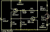
This simple circuit that can be used to flash incandescent lamps up to 10W power rating.The circuit is ideal for making flashing beacons on automobiles and other applications like that.The circuit is nothing but an astable multi vibrator based on Q1&Q2 ( BC557&BD139).The capacitor C1 is the main timing element which determines the flashing rate of the circuit.The switch S1 can be used as an ON/OFF switch.Notes.

* Power the circuit from a 12 V battery or 12V DC power supply.
* Assemble the circuit on a goood quality PCB or common board.
* A 12 v , 10W incandescent lamp can be used as the load.
* All capacitors must be rated 15V.

Read More...

Friday, April 12, 2013

Multipurpose Circuit For Telephones

This add-on device for telephones can be connected in parallel to the telephone instrument. The circuit provides audio-visual indication of on-hook, off-hook, and ringing modes. It can also be used to connect the telephone to a  CID (caller identification device) through a re-lay and also to indicate tapping or misuse of telephone lines by sounding a buzzer.

In on-hook mode, 48V DC supply is maintained across the telephone lines. In this case, the bi-colour LED glows in green, indicating the idle state of the telephone. The value of resistor  R1 can be changed some-what to adjust the  LED glow, with-out loading the telephone lines (by trial and error).  In on-hook mode of the hand-set, potentiometer VR1 is so adjusted that base of  T1 (BC547) is forward biased, which, in turn, cuts off transistor T2 (BC108). While adjusting  potmeter  VR1, en-sure that the  LED glows only in green and not in red.

Multipurpose Circuit For Telephones Circuit Diagram
Multipurpose Circuit For Telephones circuit Diagram

When the handset is lifted, the volt-age drops to around 12V  DC. When this happens, the voltage across transistor T1’s base-emitter junction falls below its conduction level to cut it off. As a result transistor pair T2-T3 starts oscillating and the piezo-buzzer starts beeping (with switch S1 in on position). At the same time, the bi-colour LED glows in red. In ringing mode, the bi-colour LED flashes in green in synchronization with the telephone ring. A  CID can be connected using a relay.

The relay  driver  transistor can be connected via point  A as shown in the circuit. To use the circuit for warning against misuse,  switch  S1 can be left in on position to activate the piezo buzzer when anyone tries to tap the telephone line. (When the telephone  line is tapped, it’s  like the off-hook mode of the telephone hand-set.)  Two 1.5V pencil cells can provide Vcc1 power supply, while a separate power supply for Vcc2 is recommended to avoid draining the battery. However, a single 6-volt supply source can be used in con-junction with a 3.3V zener diode to cater to both Vcc2 and Vcc1 supplies.

Source:http://www.ecircuitslab.com/2011/10/multipurpose-circuit-for-telephones.html


Read More...

Stereo Line Driver Circuit Using Transistor

This is the schematic diagram of a low cost stereo line driver. The circuit is based only two transistors and few passive components. This is the figure of the circuit.


The description work of the circuit is each BC 109C transistor is wired as an emitter follower for driving each channel. The voltage gain of the emitter follower is unity, but it has a high current gain and low output impedance, ideal for driving long cables. The output impedance is around 16 Ohms at 1KHz.Since voltage gain is unity power amplifiers must be used at the listening end in order to drive loud speakers. The circuit can be powered from a 12V battery or 12V DC power supply. A power amplifier is needed at the listening end because the emitter follower has only unity voltage gain. The inputs and outputs must be connected with respect to ground as shown in circuit.

Read More...

Dew Sensitive Switch Circuit Using LM358

This is a simple design circuit that can be used to switch ON or OFF a device when the dew present in the surrounding atmosphere crosses a set value. This circuit uses a dew sensitive resistive element and a comparator based on LM 358 to perform the above said operation. This is the figure of the circuit.


In operation of the circuit, at normal condition the resistance of dew sensor element will be low and so the voltage drop across it. So the voltage at the non inverting pin of LM358 (IC1) will be less than the voltage at the inverting input of the LM358.So the output of the op amp will be low. This keeps the opto coupler (MCT2E) deactivated. When the dew increases the resistance of the element increases and so do the voltage across it. Now the voltage at the non inverting pin of LM358 (IC1) will be higher than the voltage at the inverting input of the LM358.So the output of the op amp will be switched to high. This in turn activates the opto coupler. The LED glows to indicate it. As a result we get an opto coupler activated and de activated according to the amount of dew in the atmosphere. The output pins of opto coupler pin (5&4) can be used to control the external device.

Diode D1, resistors R6&R3 and capacitor C1 is employed here to derive the power for the circuit directly from mains. The dew sensor is hard to find in market. But it can be easily obtained from a old VCR. Also the type no of the sensor is not so important here. Try with any thing you get. I used one from a old Hitachi VCR. LM 358 is a dual op amp. Here only one op amp inside it is used.


Read More...

Thursday, April 11, 2013

How to Make a Dual Tone Siren Circuit

This electronic siren gives out a continuously varying high amplitude sound. Since the supply voltage is not critical, it can be used in cars, motor cycles or at home. It can replace the ordinary call bell. - . The circuit consists of two separate free running multivibrator and an oscillator.

A free running or astable multivibrator is one which has two quasi-stable states and the output of one stag is connected to the input of the other through a coupling capacitor.

Since both the states are quasi-stable, the output attained is continuously varying in nature i.e. high, low high low-.

 The output is in the form low pulses, the frequency of which depends on the base biasing resistor and the coupling capacitor, When these resistances and condensers for both the stages are of different values, the output ` wave form is rectangular; this is because the time constant of the two quasi-stable states becomes different.

If this time constant of the two, states is made the same, the output obtained then is square wave. Two states of the multivibrator are made identical by the use of the same values of components.

The components used in the circuit (Fig). result in a square wave output and the time constant selected is so as to give a fairly good rise and fall of the siren.

However, one may change the value of coupling capacitors to get any other desired time constant. The second unit is an oscillator section. The condenser connected at the output is the feed back condenser. It determines the tone of the siren.

Higher the value of the condenser the lower is the pitch. for high pitch sound (generally used in siren) feed-back condenser ranging from 0.047 uf to 0.1 mfd should be selected. The speaker may be metallic case (horn type) or small planer cone. The metallic cone horn gives better results.


Parts for dual tone siren circuit

R1,R2,R5,R6= 22K
R3,R4 = 2K2
R7 = 10 Ohms, 1 watt
C1,C2,C4 = 0.1uF
C3 = 22uF/25V
T1,T2 = BC557
T3 = BC547
T4 = 2N2907 or 8550

Read More...

USB Switch Schematic Circuit

Anyone experimenting or developing USB ported peripheral hardware soon be comes irritated by the need to disconnect and connect the plug  in order to reestablish communication with the PC. This process is necessary for example each time the peripheral equipment is reset or a new version of the firmware is installed. As well as tiresome it eventually leads to excessive contact wear in the USB connector. The answer is to build this electronic isolator which disconnects the peripheral device at the touch of a button. This is guaranteed to reduce any physical wear and tear and restore calm once again to the workplace. 

Circuit image :
 USB Switch-Image
USB Switch Schematic Circuit Image

The circuit uses a quad analogue switch type 74HC4066. Two of the switches in the package are used to isolate the data path. The remaining two are used in a classic bistable flip-flop configuration which is normally built using transistors. A power MOSFET switches the power supply current to the USB device.  Capacitor C2 ensures that the flip flop always  powers-up in a defined state when plugged  into the USB socket (‘B’ in the diagram). 

The  peripheral device connected to USB socket ‘A’  will therefore always be ‘not connected’ until  pushbutton S2 is pressed. This flips the bistable, turning on both analogue gates in the data lines and switching the MOSFET on. The  PC now recognises the USB device. Pressing  S1 disconnects the device.
Circuit diagram :
USB Switch-Circuit-daigram
USB Switch Schematic Circuit Diagram

The circuit does not sequence the connections as a physical USB connector does; the power supply connection strips are slightly longer than the two inner data carrying strips to ensure the peripheral receives power before the data signals are connected. The electronic switch does not suffer from the same contact problems as the physical  connector so these measures are not required in the circuit. The  simple circuit can quite easily be constructed on a small  square of perforated strip-board. 

The design uses the 74HC(T)4066 type analogue switch, these have  better characteristics compared to the standard 4066 device. The USB switch is suitable for both low-speed (1.5 MBit/ s) and full-speed (12 MBit/s) USB ports applications but the proper ties of the analogue switches and perf-board construction  will not support hi-speed (480 MBit/s) USB operation. 

The IRFD9024 MOSFET can pass a current of  up to 500 mA to the peripheral device with-out any problem.
 
 
 http://streampowers.blogspot.com/2012/07/touch-switchs.html
Read More...

Wednesday, April 10, 2013

Motor driver L298 Circuit

DC motor driver with H-Bridge IC L293D
IC H Bridge DC motor driver L298 has two H-Bridge circuit in it, so it can be used to download the drive two DC motors. H Bridge DC motor driver L298 each can deliver currents up to 2A. However, in use, the H Bridge DC motor driver L298 can be used in parallel, so the ability to deliver the H Bridge DC motor driver L298 flow into 4A. The consequences of the installation of H Bridge L298 DC motor driver with the parallel mode, you need 2 pieces Bridge H L298 DC motor driver to control two DC motors using H bridge DC motor driver L298 in parallel mode.
H Bridge Pin IC L298 DC motor driver which is connected in parallel operation mode:
* OUT1 connected to OUT4.
* OUT2 OUT3 linked.
* IN1 is connected to IN4.
* IN2 connected to IN3.
* ENABLE ENABLE A linked to B.

OUT1/OUT4 and OUT2/OUT3 associated with DC motors to be controlled.

Please note that the output of the L298 does not have a safety diode. Thus, the need to add two diodes - flyback diodes, with appropriate current capability, at any point output.
Read More...