Showing posts with label amplifier. Show all posts

Sunday, December 22, 2013

Motional Feed Back Amplifier

This concept has appeared long back in Practical Electronics a UK based Magazine. Based on this concept I designed this circuit during 1981 to 1986 with lots of field trials and modifications, the design was frozen in 1986. I have assembled so many amplifiers for me and for my friends based on this design with various power levels. They are still kicking in so many houses. This concept can be applied to any existing amplifier also. You must listen to believe the crystal clear thumping bass response. crystal clear mid and hi frequencies. Good transient response with very low distortion. Hope you guys  will enjoy the reproduction of this amplifier.

In the art of audio sound reproduction it is well-known that the dynamic loudspeaker is more nonlinear and generates more distortion than all the other system components combined. This is particularly true at low frequencies which require large cone excursions where the stiffness of both the inner spider and the outer surround increases rapidly as the cone approaches its peak displacement, resulting in a nonlinear suspension compliance generating high distortion.

For example, in a typical high fidelity sound system at a frequency of about 35 Hz the total harmonic distortion of the amplifier might be of the order of 0.01%, whereas the distortion of the loudspeaker might range from about 3.0% to about 50.0%, depending upon the loudness. If this cone motion can be sensed and given as a feed back to the earlier stage of the amplifier, this distortion can be reduced dramatically.

Circuit diagram:

motional-feed-back-amplifier-circuit Diagram 

Motional Feed Back Amplifier Circuit Diagram

Motional Feedback (MFB) was a speaker system developed in the early 1970s by Philips Holland. It introduced a feedback system to the woofers of HiFi loudspeakers, enabling them to achieve a more extended low frequency response in a relatively small enclosure. The key benefits are a very controlled bass response. Any distortion induced by the enclosure or the woofer itself is immediately corrected by the feedback. These hand-built speakers were sounding very good and were quite expensive.

As a different approach, instead of using the cone movement, the current flow through the voice can be sensed (the current is proportional to cone movement) and can be used as a cone movement feedback. This novel idea is used in this amplifier design (I don’t claim any originality; this idea has appeared in Practical Electronics UK Magazine – long back – They might have even patented it).the amplifier used here is a standard Philips audio application circuit, with a specification of 40 Watt RMS @ < 0.06% Total Harmonic Distortion into 8 ohms impedance speaker and having a frequency response from 20Hz to 100 KHz, suitably modified for our application.

Powersupply Circuit:

power-supply-for-motional-feed-back

Motional Feed Back Amplifier Powersupply Circuit Diagram

The amplifier is a conventional class B directly coupled quasi complimentary out put stage, operating with single 56Volt supply (no need for a regulated or dual power supply). BC157 is the pre-driver and half supply stabilizer. BD 139 is the driver, a BD139 and a BD140 complimentary pair out put driver stage with 2N3055 as final out put stage. The speaker voice coil current is sensed through 0.47 ohms resistance connected from speaker one end to ground. This signal is given as negative fed back to previous stage through 470 ohms. The half supply at speaker coupling capacitor can be adjusted by varying the 39K resistance (if required you may fix a 100K pre set in the place of 39K and adjust for half supply with no in put signal at junction of both 0.47 ohms of out put transistors and speaker coupling capacitor).

The quiescent current through output transistors can be adjusted with 22 ohms in series with two bias diodes 1N4007. The value for 50mA quiescent current will lie between 15 to 33 ohms for a supply of 56volts. The amplifier can be protected with a simple 1.5Amp fast acting fuse in the positive power supply. the amplifier can be assembled on 40watt Philips amplifier application board or on any standard plain straight line board. All the three driver transistors require cooling clips. (Standard TO220 casing cooling fins). Out put transistors require a good quality extruded alloy heat sink with insulating mounting kit and with a smear of silicon conductive grease, for good conductance of heat.

Read More...

Tuesday, September 24, 2013

Playback Amplifier For Cassette Deck

For some time now, there have been a number of tape cassette decks available at low prices from mail order businesses and electronics retailers. Such decks do not contain any electronics, of course. It is not easy to build a recording amplifier and the fairly complex magnetic biasing circuits, but a playback amplifier is not too difficult as the present one shows. The stereo circuits in the diagram, in conjunction with a suitable deck, form a good-quality cassette player. The distortion and frequency range (up to 23 kHz) are up to good standards. Moreover, the circuit can be built on a small board for incorporation with the deck in a suitable enclosure. Both terminals of coupling capacitor C1 are at ground potential when the amplifier is switched on.

Cassette Deck Playback Amplifier Circuit DiagramBecause of the symmetrical ±12 V supply lines, the capacitor will not be charged. If a single supply is used, the initial surge when the capacitor is being charged causes a loud click in the loudspeaker and, worse, magnetizes the tape. The playback head provides an audio signal at a level of 200–500 mV. The two amplifiers raise this to line level, not linearly, but in accordance with the RIAA equalization characteristic for tape recorders. Broadly speaking, this characteristic divides the frequency range into three bands:
  • Up to 50 Hz, corresponding to a time constant of 3.18 ms, the signal is highly and linearly amplified.
  • Between 50 Hz and 1.326 kHz, corresponding to a time constant of 120 µs, for normal tape, or 2.274 kHz, corresponding to a time constant of 70 µs, for chromium dioxide tape, the signal is amplified at a steadily decreasing rate.
  • Above 1.326 kHz or 2.274 kHz, as the case may be, the signal is slightly and linearly amplified. This characteristic is determined entirely by A1 (A1’). To make the amplifier suitable for use with chromium dioxide tape, add a double-pole switch (for stereo) to connect a 2.2 kΩ resistor in parallel with R3 (R3’). The output of A1 (A1’) is applied to a passive high-pass rumble filter, C3-R5 (C3’-R5’) with a very low cut-off frequency of 7 Hz. The components of this filter have exactly the same value as the input filter, C1-R1 (C1’-R1’). The second stage, A2 (A2’) amplifies the signal ´100, that is, to line level (1V r.m.s.).
Read More...

Sunday, May 5, 2013

Reliable 6 Watt Hi Fi Audio Amplifier Using TDA2613

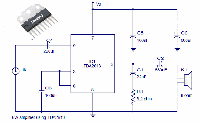
A 6 watt audio amplifier circuit using TDA2613 is shown here. TDA2613 is an integrated Hi-Fi  audio amplifier IC from Philips Semiconductors. The IC is switch ON / switch OFF click proof, short circuit proof, thermally protected and is available in 9 pin single in line plastic package. In the given circuit, TDA2613 is wired to operate from a single supply.

Capacitor C4 is the input DC decoupler while capacitors C5, C6 are power supply filters. Input audio is fed to the non inverting input through capacitor C4. Inverting input and Vp/2 pins of the IC are tied together and connected to ground through capacitor C3. Capacitor C2 couples the speaker to the ICs output and the network comprising of capacitor C1 and resistor R1 improves the high frequency stability.

Circuit diagram

6 Watt Hi Fi Audio Amplifier using TDA2613

Notes.
  • Assemble the circuit on good quality PCB.
  • Supply voltage (Vs) can be anything between 15 to 24V DC.
  • Heat sink is necessary for TDA2613.
  • Do not give more than 24V to TDA2613.
Read More...

Thursday, April 11, 2013

4 X 15 Watt Mini Power Amplifier

A lot of electronic circuits in the domain of audio amplifiers are already been published here. This circuit is a little different because it is a four channel amplifier. Each channel of this amplifier can deliver an output of 15Watts into a 4 ohm speaker. The amplifier can be operated from a single 12V DC supply and this makes it possible to use this amplifier in car audio applications too.

4 X 15 Watt Mini Power Amplifier Circuit diagram :
4X15W-amplifier-circuit Diagram

The circuit is based on the 15W BTL X 2 channel audio power amplifier IC TA8215 from Toshiba. Even though chip is specifically designed for car audio applications it can be also used for home audio applications. Two TA8215 ICs are used here in order to obtain a 4 channel amplifier system. The circuit is designed almost exactly as per the application diagram in the ICs datasheet. Pins 7 and 19 are the Vcc pins of the ICs internal integrated power amplifier stages and these pins are connected to the positive supply. Pin 9 is the Vcc pin for ICs internal preamplifier and it is also connected to the positive supply. Pins 13 and 14 are the internal power amplifiers ground pins and they are tied together and connected to the ground.
The internal preamplifier’s ground pin (pin5) is connected to the common ground through a 10 Ohm resistor which makes the input ground separated from the common ground by a resistance of 10 ohms and this improves the noise rejection. The 100uF capacitor works as a power supply de-coupler. The resistor networks connected to the output lines of each amplifier improves the high frequency stability. The variable resistors (R3, R4, R12 and R13) works as the volume controller for the corresponding channels.

Notes :
  • Assembling the circuit on a good quality PCB is a must for obtaining optimum sound quality.
  • Use 12V DC for powering the circuit.
  • The ICs must be fitted with adequately sized heat sinks.
  • R3, R4, R12 and R13 serves as volume controllers.
  • K1 to K4 can be 4 Ohm, 20W speakers.
  • This amplifier circuit can be used in a variety of applications such as car audio systems, home theater systems, personal audio systems, public address systems etc.
Source : http://www.ecircuitslab.com/2012/08/4-x-15-watt-mini-power-amplifier.html
Read More...

Wednesday, April 10, 2013

25 W AUDIO AMPLIFIER MOSFET IRF530 IRF9530

25 W AUDIO AMPLIFIER MOSFET IRF530-IRF9530

The supply rails prudentially voltage was kept at the rather low value of + and - 32V.


Note:


  • Q6 & Q7 must have a small U-shaped heatsink.
  • Q8 & Q9 must be mounted on heatsink.
  • Adjust R11 to set quiescent current at 100mA (best measured with an Avo-meter connected in series to Q8 Drain) with no input signal.
  • A correct grounding is very important to eliminate hum and ground loops. Connect to the same point the ground sides of R1, R4, R9, C3 to C8. Connect C11 to output ground. Then connect separately the input and output grounds to power supply ground.


Read More...

Sunday, April 7, 2013

25W Hi Fi Power Amplifier Circuit

25 W Hi-Fi power amplifier circuit is a one of simple design that’s build by transistor NPN and PNP. The output devices are MJL4281A (NPN) and MJL4302A (PNP), and feature high bandwidth, excellent SOA (safe operating area), high linearity and high gain. Driver transistors are MJE15034 (NPN) and MJE15035 (PNP). All devices are rated at 350V, with the power transistors having 230W power dissipation and the drivers are 50W. The amp may also be operated at lower supply voltages for less power, but I do not recommend less than ±18V, which will provide around 15W into 8 ohms. This supply voltage (approximately) may be obtained by using a 15-0-15V transformer. This figure is show the circuit and operation of the circuit.


The supply voltage should be a maximum of ±25V. This supply is easily obtained from a 20-0-20V transformer. All resistors should be 1/4W or 1/2W 1% metal film for lowest noise, with the exception of R9, R10 and R15 which should be 1/2W types, and R13, R14 must be 5W wire wound. The bootstrap capacitor (C5) needs to be rated at least 25V, but the other electrolyc can be any voltage you have available. The potentiometer (VR1) must be a multi turn type, as the current setting is critical. Each of these amps will require a 0.25°C/W heat sink (very large). Consider using a fan or even water cooling to keep temperatures as low as possible.


Read More...

Saturday, April 6, 2013

70 Watt MOSFET Audio Amplifier

This is use the MOSFET power amplifier circuit, amplifier circuit has a very good sound quality. With the noise is quite small, thus making the amplifier circuit is suitable for you to try. Heres the circuit.
Click to view larger.

 Power amplifier with a 70Watt power is able to issue a clear voice, and very and good loud.
Read More...

Stereo Low power audio amplifier

Stereo Low power audio amplifier
Audio amplifier circuit has a power output of 2 x 2.3 Watt, which uses IC KA2206, KA22061, LA4180, LA4182, LA4183, LA4550, LA4555, LA4558. The required voltage for at least 6 volts to 13 volts DC maximum. Component takes is a ic that I mentioned above one of them, and several capacitors elco.


This Schematics low power amplifier

schematics LA4558

Component Description
C1 = 1uF
C2 = 100uF
C3 = 100uF
C4 = 100uF
C5 = 0.1uF
C6 = 470uF
C7 = 1uF
C8 = 100uF
C9 = 100uF
C10 = 100uF
C11 = 0.1uF
C12 = 470uF
ICs can use the ic which I mention above for each ic datasheet can be seen itself.
Read More...