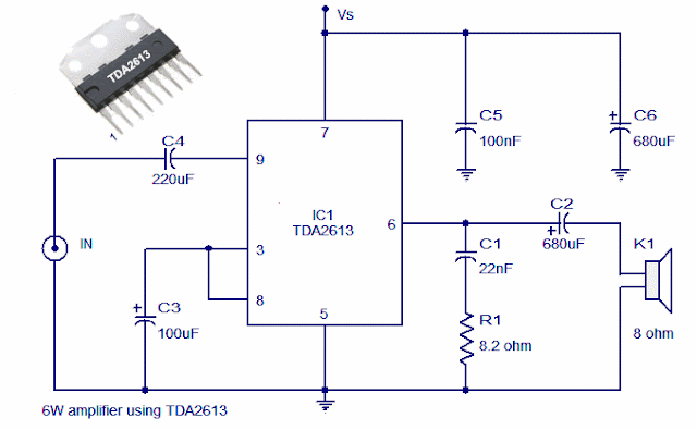
A 6 watt audio amplifier circuit using TDA2613 is shown here. TDA2613 is an integrated Hi-Fi audio amplifier IC from Philips Semiconductors. The IC is switch ON / switch OFF click proof, short circuit proof, thermally protected and is available in 9 pin single in line plastic package. In the given circuit, TDA2613 is wired to operate from a single supply.
Capacitor C4 is the input DC decoupler while capacitors C5, C6 are power supply filters. Input audio is fed to the non inverting input through capacitor C4. Inverting input and Vp/2 pins of the IC are tied together and connected to ground through capacitor C3. Capacitor C2 couples the speaker to the ICs output and the network comprising of capacitor C1 and resistor R1 improves the high frequency stability.
Circuit diagram
Capacitor C4 is the input DC decoupler while capacitors C5, C6 are power supply filters. Input audio is fed to the non inverting input through capacitor C4. Inverting input and Vp/2 pins of the IC are tied together and connected to ground through capacitor C3. Capacitor C2 couples the speaker to the ICs output and the network comprising of capacitor C1 and resistor R1 improves the high frequency stability.
Circuit diagram
Notes.
- Assemble the circuit on good quality PCB.
- Supply voltage (Vs) can be anything between 15 to 24V DC.
- Heat sink is necessary for TDA2613.
- Do not give more than 24V to TDA2613.

