Tuesday, April 30, 2013

Portable Solar Lantern

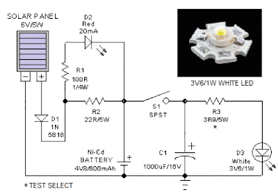
This portable solar lantern circuit uses 6 volt/5 watt solar panels are now widely available. With the help of such a photo-voltaic panel we can construct an economical, simple but efficient and truly portable solar lantern unit. Next important component required is a high power (1watt) white LED module.

When solar panel is well exposed to sunlight, about 9 volt dc available from the panel can be used to recharge a 4.8 volt /600 mAh rated Ni-Cd batterypack. Here red LED (D2) functions as a charging process indicator with the help of resistor R1. Resistor R2 regulates the charging current flow to near 150mA.

Solar Lantern Circuit Schematic
Circuit Project: Portable Solar Lantern

Assuming a 4-5 hour sunlit day, the solar panel (150mA current set by the charge controller resistor R2) will pump about 600 – 750 mAh into the battery pack. When power switch S1 is turned on, dc supply from the Ni-Cd battery pack is extended to the white LED (D3). Resistor R3 determines the LED current. Capacitor C1 works as a buffer.

Note: After construction, slightly change the values of R1,R2 and R3 up/down by trial&error method, if necessary.
Read More...

Sunday, April 21, 2013

Car Battery 12v Charger

The usual chargers of battery automotive, are simple and cheap appliances that charge continuously the battery, with a rythm of few amperes, for the time where the appliance is ON. If the holder do not close in time the charger, the battery will overcharge and her electrolytic faculty are lost with evaporation or likely exists destruction of her elements. The charger of circuit exceeds these faults. It checks electronic the situation of charge of battery and it has circuit of control with retroaction, that forces the battery charge with biggest rythm until charge completely.
Circuit diagram:
Car_baterry_charger Circuit Diagram
Car Battery 12v Charger Circuit Diaram
When charge completely, it turns on one RED led (LD2). The charger has been drawn in order to charge batteries of 12V, ONLY. What should watch it from what it manufactures the circuit, they are the cables that connect the transformer with the circuit and in the continuity the battery, should they are big cross-section, so that heat when it passes from in them the current of charge and also they do not cause fall of voltage at the way of current through them.
Adjustment
After assembling of the circuit, adjust TR1 to null value, power-up and make the following adjustments :-
  1. Without connecting the battery check that the 2 LED?s are turned on.
  2. Connect a car battery to the circuit and check that LD2 is OFF and a current (normally 2A to 4A) is flowing to the battery.
  3. Adjust TR1 until LD2 turns ON and the charge current is cut.
  4. Adjust TR1 to null value and charge the battery using the hydrometer technique (if you do not have or do not know how to use a hydrometer, then use a good condition battery and charge).

Carefully adjust TR1 so that LD2 begins to turn ON and the charge current falls to a few hundred milliamps (mA). If TR1 is set correctly then in the next round of charging you will noticed LD2 begin to flicker as the battery is being charged. When battery is completely charged, LD2 turns ON completely.TR1 does not need further adjustment anymore. Q1 is connected in line with the battery and is fired by R3, R4 and LD2. The R2, C1, TR1 and D2 sense the voltage of the battery terminal and activate Q2 when the voltage of the battery terminal exceeds the value predetermined by TR1.

When an uncharged battery is connected, the terminal voltage is low. Under this circumstance, Q2 is turned OFF and Q1 is fired in each half cycle by R3, R4 and LD2. The Q1 functions as a simple rectifier and charges the battery. If the battery terminal voltage is increased above the level that had been fixed by TR1, then Q2 shifts the control of Q1 gate. This deactivates Q1 and cuts off the current supply to the battery and turns LD2 ON indicating that the charge has been completed. Q1 and bridge rectifier GR1 should be mounted on heatsinks to prevent overheating. M1 is a 5A DC ammeter to measure the charge current.

Source :users.otenet.gr
Read More...

Saturday, April 13, 2013

Dicing With LEDs

Every self-respecting DIYer makes his own electronic dice with LEDs as spots. Then you don’t have to throw the dice anymore – just push the button. The electronics also ensures that nobody can try to improve his luck by fiddling with the dice. Too bad for sore losers! This circuit proves that an electronic die built using standard components can be made quite compact. The key component of here is a type 4060 digital counter (IC1). This IC has an integrated oscillator stage, so only two resistors (R7 and R8) and a capacitor (C7) are necessary to generate the clock signal. The clock signal is divided by various factors by the internal digital circuitry of the IC.

The division factors are designated by ‘CT’ in the IC drawing symbol. For instance, the signal on the CT3 output (pin 7) is a square wave with a frequency equal to the clock frequency divided by 23 (8). The clock signal is divided by 24 (16) on the CT4 output, by 25 (32) on the CT5 output, and so on. This means the output signals form a binary number that Dicing with LEDs counts upwards, which is naturally what a counter does.Of course, a die has only six possible values marked on the six sides of a cube. This means that at least three bits (the first three outputs) of the counter are necessary to drive a display. Eight different counter states (23) can be represented with three bits, but in this case the counter must be restricted to six states.

Dicing With LEDs Circuit diagram :

dicing-with-led-circuit diagram
dicing-with-led-schematic-circuit diagram

To make sure this happens, D11, D12 and R6 are used to reset the counter to its initial state when it reaches the seventh state, which means when it reaches a binary count of 110. When this happens, pins 4 and 5 of the IC are both logic ‘1’ (high level), which causes a logic ‘1’ to be applied to pin 12 via resistor R6. This causes the counter to be reset, which is what we want. The display consists of seven LEDs arranged in the same pattern as the usual markings on a normal die. 

This arrangement is shown in the schematic diagram. Before you begin thinking about the proper logical connections between the LEDs and the counter outputs, you can start by noting that except for the ‘1’ state there will always be two LEDs lit up at the same time. This means that only four distinct indications are necessary, instead of seven (with a total of seven LEDs).Another advantage of this is that the current consumption can be reduced by connecting pairs of LEDs in series. Resistors R1–R4 limit the current through the LEDs to approximately 2 mA. This means you have to use low-current LEDs. They are nice and bright at a current of 2 mA. Resistor R3 has a higher value because only one LED is driven via it.

For convenience, the circuit is dimensioned based on using a 9-V battery. The current consumption of the circuit depends on the number of LEDs that are illuminated, and with our prototype it varied over a range of approximately 2.5 mA to 6.5 mA. The LEDs still produce enough light even when the supply voltage is as low as 6 V, but this depends strongly on the characteristics of the low-current LEDs used in the circuit. Diodes D8–D10 and transistor T1 are necessary to enable all the states of a normal die to be shown. By that, we primarily mean the states with two or three spots, which must be located diagonally. For readers who want to delve more deeply into the design, the following table shows the six different binary states, which LEDs are lit up for each state, and the number of spots shown by the die.

The die is operated by switch S1. In the quiescent state, the break contact of S1 is closed and the oscillator is stopped because the input of the oscillator stage is connected to ground via the switch. When S1 is pressed, the oscillator starts running and causes the states of the LEDs to change at a rate of 1 kHz, which is too fast to follow with the naked eye. This high frequency ensures that the state of the die is purely random when S1 is released, so there is no regularity or pattern in the results. The circuit can be assembled on a small piece of perforated prototyping board. Fit the LEDs in exactly the same pattern as shown in the schematic diagram, since otherwise the spot patterns will not correspond to a real die. When you have assembled the circuit board, fit it in a plastic enclosure along with a 9-V battery to provide power.

Source :  http://www.ecircuitslab.com/2011/05/dicing-with-led.html
Read More...

Efficient Fan Speed Controller

A partial approach to quietening noisy PCs can additionally be to reduce the pace of interior cooling lovers. Low-cost fan speed controllers are available, however they continuously hire inefficient, heat-generating linear regulators and include no temperature remarks mechanism. This concept makes use of a with no trouble available, cheap in-car cell phone charger. The majority of these use common circuitry and require only minor amendments to function as efficient fan speed controllers complete with temperature feedback. Most in-car chargers are based on the nicely-known MC34063 DC-DC switchmode IC.

When used for charging cell phones, the open-circuit output voltage is in most cases set to between 7V and 9V. This is carried out with a easy voltage divider across the output, the centre level of which joins to the feedback input (pin 5) of the MC34063. To make the output voltage var-iable with air temperature, first exchange the higher resistor of the divider with a four.7kΩ resistor in collection with a four.7kΩ trimpot. The decrease half of the divider is then changed with a 470Ω resistor in sequence with a 500Ω NTC thermistor. These prices are simplest a information and may additionally be diverse to suit totally different thermistor and fan types.

Circuit diagram:

Efficient Fan Speed Controller Circuit Diagram

Note that component lead size should be minimised to avoid introducing noise into the remarks circuitry. Getting the best fan beginning voltage is a topic of trial and error. The prices shown on the circuit supply a beginning voltage of about 6.8V at room temperature however trimpot VR1 can be utilized to lift this voltage as vital. The output can then upward thrust to about 10V if the interior temperature upward viasts sufficiently. The 4.7kΩ resistor can be reduced to three.9kΩ and VR1 adjusted to give a lower beginning voltage if the fan pace is still too excessive at 7V. After operating for one hour or so, the fan voltage as set with the help of the interior case temperature thermistor on my PC settled at 7.4V.

Suitable chargers are to be had from Oatley Electronics, Cat. No. 2D0074. They’re presently listed at $5 for two, which is less than the associated fee of the MC34063 ICs alone! Data on the MC34063 can also be downloaded from www.onsemi.com and a useful construction aid is to be found at www.nomad.ee/micros/mc34063. Finally, note that now not all chargers have an output filter capacitor put in. Typically, this is a 220µF 10V or 16V electrolytic sort. To save just a few cents, the producers every so often go away this component out, relying on the mobile’s battery to operate the filtering process. If this element is missing from your charger’s PC board, it will have to be put in ahead of the availability is used.


http://www.ecircuitslab.com/2011/08/efficient-fan-speed-controller.html
Read More...

Automatic AC Power Switch

Electrical appliances accidentally left on  in (holiday) homes left unoccupied for a  brief or a protracted length devour power  unnecessarily and may existing a fire hazard. Everyone shall be accustomed to those  nagging thoughts, a quantity of miles down the  highway from the home: “Did I remember  to change off the espresso machine? The  milds? The oven?” 

Circuit diagram :
Automatic AC Power Switch Circuit Diagram

Hotel rooms are regularly equipped with a  swap near the main door which allows the facility supply to the entire thing in  the room simplest when the plastic card (which  may contain a chip or have a magnetic strip  or a sample of holes) that serves because the room  secret's inserted. The circuit thought given here  to modify off gentles and different home equipment is  alongside the identical lines. The answer is distinctly easy. 

A reed contact is suited for the body of the main entrance door, and a matching magnet  is hooked up to the door itself such that when  the door is closed the reed contact is also  closed. To allow power to the house, press  S1 briefly. Relay RE1 will pull in and complete  the circuit for all of the AC powered home equipment in  the house. The relay will be held in even after  the button is liberated by means of the second relay contact and the reed contact (‘latching’ function). 

As quickly as the primary entrance door is  opened, the reed contact may even open.  This in flip releases the latch circuit and  consequently the relay drops out. The  various linked home equipment will thus  routinely and that inevitably be switched  off as quickly as the house is left. The circuit is mainly designed for  small vacation properties, where this mode  of operation is especially sensible. Of course, for any circuit that deals in AC  powerline voltages, we should mention  the next caution. 

Caution:
shock hazard! Construction and connection of this circuit  will have to simplest be carried out by suitably-qualified  personnel, and all applicable electrical safety  rules must be observed. In particular, it  is essential to be positive that the relay chosen is  acceptable to be used at domestic AC grid volt-ages and is suitably rated to hold the required  current.


http://www.ecircuitslab.com/2012/04/automatic-ac-power-switch.html
Read More...

Motorbike Alarm

This simple to build alarm can be fitted in bikes to protect them from being stolen. The tiny circuit can be hidden anywhere, without any complicated wiring. Virtually, it suits all bikes as long as they have a battery. It doesnt drain out the battery though as the standby current is zero. The hidden switch S1 can be a small push-to-on switch, or a reed switch with magnet, or any other similar simple arrangement. The circuit is designed around a couple of low-voltage MOSFETs configured as monostable timers. Motorbike key S2 is an ignition switch, while switch S3 is a tilt switch. Motorbike key S2 provides power supply to the gate of MOSFET T2, when turned on. 
 
When you turn ignition off using key S2, you have approximately 15 seconds to get off the bike; this function is performed by resistor R6 to discharge capacitor C3. Thereafter, if anyone attempts to get on the bike or move it, the alarm sounds for approximately15 seconds and also disconnects the ignition circuit. During parking, hidden switch S1 is normally open and does not allow triggering of mosfet T1. But when someone starts the motorbike through ignition switch S2, MOSFET T2 triggers through diode D1 and resistor R5. Relay RL1 (12V, 2C/O) energises to activate the alarm (built around IC1) as well as to disconnect the ignition coil from the circuit. Disconnection of the ignition coil prevents generation of spark from the spark plug. Usually, there is a wire running from the alternator to the ignition coil, which has to be routed through one of the N/C1 contacts of relay RL1 as shown in Fig.1 Fig.2 shows the pin configurations of SCR BT169, MOSFET BS170 and transistor BC548.
 
Circuit diagram :

Motorbike Alarm-Circuit-Diagram
 Motorbike Alarm Circuit Diagram
Motorbike Alarm-Pin Configurations :

Motorbike Alarm-Pin configurations
Pin configurations of BT169, BS170 and BC548
 
Also, on disconnection of the coil, sound generator IC UM3561 (IC1) gets power supply through N/O2 contact of relay RL1. This drives the darlington pair built around T3 and T4 to produce the siren sound through loudspeaker LS1.  To start the vehicle, both hidden switch S1 and ignition key S2 should be switched on. Otherwise, the alarm will start sounding. Switching on S1 triggers SCR1, which, in turn, triggers MOSFET T1. MOSFET T1 is configured to disable MOSFET T2 from functioning. As a result, MOSFET T2 does not trigger and relay RL1 remains de-energised, alarm deactivated and ignition coil connected to the circuit.  Connection to the ignition coil helps in generation of spark from the spark plug. Keeping hidden switch S1 accessible only to the owner prevents the bike from pillaging. Tilt switch S3 prevents attempt to move the vehicle without starting it. Glass-and metal-bodied versions of the switch offer bounce-free switching and quick break action even when tilted slowly. 
 
Unless otherwise stated, the angle by which the switch must be tilted to ensure the contact operation (operating angle), must be approximately 1.5 to 2 times the stated differential angle. The differential angle is the measure of the just closed position to the just open position. The tilt switch has characteristics like contacts make and break with vibration, return to the open state at rest, non-position sensitivity, inert gas and hermetic sealing for protection of contacts and tin-plated steel housing. If you find difficulty in getting the tilt switch, you may replace it with a reed switch (N/O) and a piece of magnet. The magnet and the reed switch should be mounted such that the contacts of the switch close when the bike stand is lifted up from rest.
 
 
Streamcircuits
Read More...

Friday, April 12, 2013

5 Zone Alarm System

This is a complete alarm system with 5 independent zones suitable for a small office or home environment. It uses just 3 CMOS ICs and features a timed entry / exit zone, 4 immediate zones and a panic button. There are indicators for each zone a "system armed" indicator. The schematic is as follows:


5 zone alarm


Circuit Notes
Each zone uses a normally closed contact. These can be micro switches or standard alarm contacts (usually reed switches). Suitable switches can be bought from alarm shops and concealed in door frames, or window ledges.

Zone 1 is a timed zone which must be used as the entry and exit point of the building. Zones 2 - 5 are immediate zones, which will trigger the alarm with no delay. Some RF immunity is provided for long wiring runs by the input capacitors, C1-C5. C7 and R14 also form a transient suppressor. The key switch acts as the Set/Unset and Reset switch. For good security this should be the metal type with a key.

Operation
At switch on, C6 will charge via R11, this acts as the exit delay and is set to around 30 seconds. This can be altered by varying either C6 or R11. Once the timing period has elapsed, LED6 will light, meaning the system is armed. LED6 may be mounted externally (at the bell box for example) and provides visual indication that the system has set. Once set any contact that opens will trigger the alarm, including Zone 1. To prevent triggering the alarm on entry to the building, the concealed re-entry switch must be operated. This will discharge C6 and start the entry timer. The re-entry switch could be a concealed reed switch, located anywhere in a door frame, but invisible to the eye. The panic switch, when pressed, will trigger the alarm when set. Relay contacts RLA1 provide the latch, RLA2 operate the siren or buzzer.
 
 
 http://streampowers.blogspot.com/2012/07/5-zone-alarm-system.html
Read More...

Multipurpose Circuit For Telephones

This add-on device for telephones can be connected in parallel to the telephone instrument. The circuit provides audio-visual indication of on-hook, off-hook, and ringing modes. It can also be used to connect the telephone to a  CID (caller identification device) through a re-lay and also to indicate tapping or misuse of telephone lines by sounding a buzzer.

In on-hook mode, 48V DC supply is maintained across the telephone lines. In this case, the bi-colour LED glows in green, indicating the idle state of the telephone. The value of resistor  R1 can be changed some-what to adjust the  LED glow, with-out loading the telephone lines (by trial and error).  In on-hook mode of the hand-set, potentiometer VR1 is so adjusted that base of  T1 (BC547) is forward biased, which, in turn, cuts off transistor T2 (BC108). While adjusting  potmeter  VR1, en-sure that the  LED glows only in green and not in red.

Multipurpose Circuit For Telephones Circuit Diagram
Multipurpose Circuit For Telephones circuit Diagram

When the handset is lifted, the volt-age drops to around 12V  DC. When this happens, the voltage across transistor T1’s base-emitter junction falls below its conduction level to cut it off. As a result transistor pair T2-T3 starts oscillating and the piezo-buzzer starts beeping (with switch S1 in on position). At the same time, the bi-colour LED glows in red. In ringing mode, the bi-colour LED flashes in green in synchronization with the telephone ring. A  CID can be connected using a relay.

The relay  driver  transistor can be connected via point  A as shown in the circuit. To use the circuit for warning against misuse,  switch  S1 can be left in on position to activate the piezo buzzer when anyone tries to tap the telephone line. (When the telephone  line is tapped, it’s  like the off-hook mode of the telephone hand-set.)  Two 1.5V pencil cells can provide Vcc1 power supply, while a separate power supply for Vcc2 is recommended to avoid draining the battery. However, a single 6-volt supply source can be used in con-junction with a 3.3V zener diode to cater to both Vcc2 and Vcc1 supplies.

Source:http://www.ecircuitslab.com/2011/10/multipurpose-circuit-for-telephones.html


Read More...

Stereo Line Driver Circuit Using Transistor

This is the schematic diagram of a low cost stereo line driver. The circuit is based only two transistors and few passive components. This is the figure of the circuit.


The description work of the circuit is each BC 109C transistor is wired as an emitter follower for driving each channel. The voltage gain of the emitter follower is unity, but it has a high current gain and low output impedance, ideal for driving long cables. The output impedance is around 16 Ohms at 1KHz.Since voltage gain is unity power amplifiers must be used at the listening end in order to drive loud speakers. The circuit can be powered from a 12V battery or 12V DC power supply. A power amplifier is needed at the listening end because the emitter follower has only unity voltage gain. The inputs and outputs must be connected with respect to ground as shown in circuit.

Read More...

Triac Light Switch as a dimers

The series of light switches this time slightly different from the voltage of work. The series of light switches can work directly on the AC power network. Light switches are using the main component of TRIAC and LDR. The circuit is very simple and the components were sold in the market.

If you want a light reception sensitivity of this circuit can be arranged then the 3.3 MOhm resistor can be replaced with a variable resistor. For more details can be seen from the following series of images.
Circuit Diagram

With Triac Light Switch series is as dimers, but dimers control performed by the reception of light around the LDR. The lower the intensity cayaha received LDR then  bright lights. For installation LDR need to be considered so as not exposed to light from the lamp directly.
Read More...

Proximity Detector

This proximity detector is constructed using an infrared diode detector. Infrared detector can be used in various equipment such as burglar alarms, touch free proximity switches for turning on a light, and solenoid-controlled valves for operating a water tap. Briefly, the circuit consists of an infrared transmitter and an infra-red receiver (such as Siemens SFH506-38 used in TV sets).

  The transmitter part consists of two 555 timers (IC1 and IC2) wired in astable mode, as shown in the figure, for driving an infrared LED. A burst output of 38 kHz, modulated at 100 Hz, is required for the infrared detector to sense the trans mission; hence the setup as shown is required.  To save power, the duty cycle of the 38kHz astable multivibrator is maintained at 10 per cent.  The receiver part has an infrared detector comprising IC 555 (IC3), wired for operation in monostable mode, followed by pnp transistor T1. Upon reception of infrared signals, the 555 timer (mono) is turned  ‘on’ and it re-mains  ‘on’ as long as the infrared signals are being received.  
 
Circuit Diagram :
Proximity Detector-Circuit-Diagram
Proximity Detector Circuit Diagram
 
When no more signals are received, the mono goes  ‘off’ after a few seconds (the delay depends on timing resistor-capacitor combination of R7-C5). The de-lay obtained using 470kilo-ohm resistor and 4.7µF capacitor is about 3 seconds. Unlike an ordinary mono, the capacitor in this mono is allowed to charge only when the reception of the signal has stopped, because of the pnp transistor T1 that shorts the charging capacitor as long as the output from IR receiver module is available (active low).  This setup can be used to detect proximity of an object moving by. Both transmitter and receiver can be mounted on a single breadboard/PCB, but care should be taken that infrared receiver is behind the infrared LED, so that the problem due to infrared leak-age is obviated.  

An object moving nearby actually reflects the infrared rays from the infrared LED. As the infrared receiver has a sensitivity angle of 60o, the IR rays are sensed within this lobe and the mono in the receiver section is triggered. This principle can be used to turn ‘on’ the light, using a relay, when a person comes nearby. The same automatically turns  ‘off’ after some time, as the person moves away. The sensitivity depends on the current limiting resistor in series with the infrared LED. It is ob-served that with in circuit resistance of preset VR1 set at 20 ohms, the object at a distance of about 25 cms can be sensed.  This circuit can be used for burglar alarms based on beam interruption, with the added advantage that the transmitter and receiver are housed in the same enclosure, avoiding any wiring problems.


http://www.ecircuitslab.com/2011/12/proximity-detector.html
Read More...

Dew Sensitive Switch Circuit Using LM358

This is a simple design circuit that can be used to switch ON or OFF a device when the dew present in the surrounding atmosphere crosses a set value. This circuit uses a dew sensitive resistive element and a comparator based on LM 358 to perform the above said operation. This is the figure of the circuit.


In operation of the circuit, at normal condition the resistance of dew sensor element will be low and so the voltage drop across it. So the voltage at the non inverting pin of LM358 (IC1) will be less than the voltage at the inverting input of the LM358.So the output of the op amp will be low. This keeps the opto coupler (MCT2E) deactivated. When the dew increases the resistance of the element increases and so do the voltage across it. Now the voltage at the non inverting pin of LM358 (IC1) will be higher than the voltage at the inverting input of the LM358.So the output of the op amp will be switched to high. This in turn activates the opto coupler. The LED glows to indicate it. As a result we get an opto coupler activated and de activated according to the amount of dew in the atmosphere. The output pins of opto coupler pin (5&4) can be used to control the external device.

Diode D1, resistors R6&R3 and capacitor C1 is employed here to derive the power for the circuit directly from mains. The dew sensor is hard to find in market. But it can be easily obtained from a old VCR. Also the type no of the sensor is not so important here. Try with any thing you get. I used one from a old Hitachi VCR. LM 358 is a dual op amp. Here only one op amp inside it is used.


Read More...

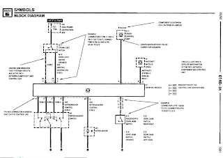
2005 Gmc 1500 Series Wiring Diagram

2005 Gmc 1500 Series Wiring Diagram


The Part of 2005 Gmc 1500 Series Wiring Diagram: power distribution, fuse block, blower motor
switch, battery, junction block, solenoid ctrl, ctrl module, oil blower motor ctrl, resistor assembly, coolant bypass solenoid ctrl, ignition voltage
Read More...

Read Wiring Diagram Symbols Ehow

Wiring Diagram Symbols on Electrical Basics Definitions   Engine Electrical
Electrical Basics Definitions Engine Electrical.


Wiring Diagram Symbols on Auto Electrical Symbols
Auto Electrical Symbols.


Wiring Diagram Symbols on How To Read Wiring Diagram Symbols Ehow
How To Read Wiring Diagram Symbols Ehow.


Wiring Diagram Symbols on Wiring Diagram Symbols Are Commonly Used In Most Wiring Diagrams
Wiring Diagram Symbols Are Commonly Used In Most Wiring Diagrams.


Wiring Diagram Symbols on Chassis Electrical   Wiring Diagrams   Wiring Diagrams   Autozone Com
Chassis Electrical Wiring Diagrams Wiring Diagrams Autozone Com.


Wiring Diagram Symbols on 1975 Mercedes Benz 280 S Wiring Diagram And Electrical Troubleshooting
1975 Mercedes Benz 280 S Wiring Diagram And Electrical Troubleshooting.


Wiring Diagram Symbols on Bmw 735i 735il 750il 1991 Electrical Troubleshooting Manual   Repair
Bmw 735i 735il 750il 1991 Electrical Troubleshooting Manual Repair.


Wiring Diagram Symbols on When Used In An Actual Circuit Diagram  The Symbols Are Often Rotated
When Used In An Actual Circuit Diagram The Symbols Are Often Rotated.


Wiring Diagram Symbols on Diagram Showing An Example Of A Floor Plan
Diagram Showing An Example Of A Floor Plan.


Wiring Diagram Symbols on My Charging Circuit  Wiring Diagram  Back Together   Justanswer
My Charging Circuit Wiring Diagram Back Together Justanswer.


Read More...

Thursday, April 11, 2013

Speech Filter

In communications receivers and microphone amplifiers for transmitting equipment, there is frequently a need for a narrow, low-frequency band-pass filter that lets only the voice band through. This band is usually defined to be the portion of the audio frequency spectrum between approximately 300 Hz and 3300 Hz. In order to implement such a filter, we have calculated the values for two fifth-order Butterworth filters having these corner frequencies and connected them in series. The result is a band-pass filter for the desired pass-band with a skirt steepness of 100 dB/decade.  The first opamp (IC1) acts as a buffer.
Speech Filter Image :
image
The circuit can be powered by a unipolar supply voltage between 5 V and 18 V, which is a broad enough range that it should always be possible to find a suitable voltage when building the filter into existing equipment. The current consumption of the filter is only a few milliampères, which should rarely pose a problem. There is fairly wide selection of suitable candidates for the opamps, since the circuit is not critical in this regard. In addition to the indicated OP27A, you could consider using a TL081N or even an old-fashioned 741.
Circuit diagram : 
Speech-Filter-Circut-Diagram
Speech Filter Circuit Diagram
Due to unavoidable spreads in component values, the pass-band curve of the filter will never be completely perfect in actual practice. However, the deviations will be very small and in any case inaudible. In the pass-band region, the gain is approximately unity. The printed circuit board design shown here allows the speech filter to be built in a very compact form, which can be an important factor if it must be fitted into existing equipment. You can quickly check the fully assembled circuit by momentarily measuring the voltages at the inputs and out-puts of the three opamps. Half of the supply voltage should be present at all of these locations.
PCB Layout :
Pcb Lyout
Parts LIST:
Resistors:
R1.R2 = 22kΩ
R3,R11,R12,R18,R19 = 100kΩ
R4 = 470Ω
R5 = 150Ω
R6 = 10kΩ
R7 = 18kΩ
R8 = 15kΩ
R9 = 33kΩ
R10 = 82kΩ
R13-R17 = 3kΩ3
Capacitors:
C1,C8,C14,C15 = 100nF
C2 = 1µF MKT
C3-C7,C11 = 22nF
C9 = 33nF
C10 = 18nF
C12 = 10nF
C13 = 4nF7
C16,C17 = 10µF 16V
Semiconductors:
IC1,IC2,IC3 = OP27A, TL081CN
Miscellaneous:
Bt1 = 9-V battery
 
 
Source by : Streampowers
Read More...

2003 Chevrolte Monte Carlo 3400 Wiring Diagram

2003 Chevrolet Monte Carlo 3400 Wiring Diagram


The Part of 1957-58 Dodge 4-Way Power Seat Wiring Diagram: compressor control, power
distribution, schematics, battery, ignition voltage, junction block, refrigerant pressure sensor, ctrl module, body ctrl module, compressor cluth, instrument panel lamp, fuse supply voltage,
Read More...

How to Make a Dual Tone Siren Circuit

This electronic siren gives out a continuously varying high amplitude sound. Since the supply voltage is not critical, it can be used in cars, motor cycles or at home. It can replace the ordinary call bell. - . The circuit consists of two separate free running multivibrator and an oscillator.

A free running or astable multivibrator is one which has two quasi-stable states and the output of one stag is connected to the input of the other through a coupling capacitor.

Since both the states are quasi-stable, the output attained is continuously varying in nature i.e. high, low high low-.

 The output is in the form low pulses, the frequency of which depends on the base biasing resistor and the coupling capacitor, When these resistances and condensers for both the stages are of different values, the output ` wave form is rectangular; this is because the time constant of the two quasi-stable states becomes different.

If this time constant of the two, states is made the same, the output obtained then is square wave. Two states of the multivibrator are made identical by the use of the same values of components.

The components used in the circuit (Fig). result in a square wave output and the time constant selected is so as to give a fairly good rise and fall of the siren.

However, one may change the value of coupling capacitors to get any other desired time constant. The second unit is an oscillator section. The condenser connected at the output is the feed back condenser. It determines the tone of the siren.

Higher the value of the condenser the lower is the pitch. for high pitch sound (generally used in siren) feed-back condenser ranging from 0.047 uf to 0.1 mfd should be selected. The speaker may be metallic case (horn type) or small planer cone. The metallic cone horn gives better results.


Parts for dual tone siren circuit

R1,R2,R5,R6= 22K
R3,R4 = 2K2
R7 = 10 Ohms, 1 watt
C1,C2,C4 = 0.1uF
C3 = 22uF/25V
T1,T2 = BC557
T3 = BC547
T4 = 2N2907 or 8550

Read More...

4 X 15 Watt Mini Power Amplifier

A lot of electronic circuits in the domain of audio amplifiers are already been published here. This circuit is a little different because it is a four channel amplifier. Each channel of this amplifier can deliver an output of 15Watts into a 4 ohm speaker. The amplifier can be operated from a single 12V DC supply and this makes it possible to use this amplifier in car audio applications too.

4 X 15 Watt Mini Power Amplifier Circuit diagram :
4X15W-amplifier-circuit Diagram

The circuit is based on the 15W BTL X 2 channel audio power amplifier IC TA8215 from Toshiba. Even though chip is specifically designed for car audio applications it can be also used for home audio applications. Two TA8215 ICs are used here in order to obtain a 4 channel amplifier system. The circuit is designed almost exactly as per the application diagram in the ICs datasheet. Pins 7 and 19 are the Vcc pins of the ICs internal integrated power amplifier stages and these pins are connected to the positive supply. Pin 9 is the Vcc pin for ICs internal preamplifier and it is also connected to the positive supply. Pins 13 and 14 are the internal power amplifiers ground pins and they are tied together and connected to the ground.
The internal preamplifier’s ground pin (pin5) is connected to the common ground through a 10 Ohm resistor which makes the input ground separated from the common ground by a resistance of 10 ohms and this improves the noise rejection. The 100uF capacitor works as a power supply de-coupler. The resistor networks connected to the output lines of each amplifier improves the high frequency stability. The variable resistors (R3, R4, R12 and R13) works as the volume controller for the corresponding channels.

Notes :
  • Assembling the circuit on a good quality PCB is a must for obtaining optimum sound quality.
  • Use 12V DC for powering the circuit.
  • The ICs must be fitted with adequately sized heat sinks.
  • R3, R4, R12 and R13 serves as volume controllers.
  • K1 to K4 can be 4 Ohm, 20W speakers.
  • This amplifier circuit can be used in a variety of applications such as car audio systems, home theater systems, personal audio systems, public address systems etc.
Source : http://www.ecircuitslab.com/2012/08/4-x-15-watt-mini-power-amplifier.html
Read More...

Flugzeugepipern7311y

Piper Aircraft on Piper Aircraft Unveils The Piper Matrix  A Cabin Class  Six Seat
Piper Aircraft Unveils The Piper Matrix A Cabin Class Six Seat.


Piper Aircraft on Full Piper Aircraft Library
Full Piper Aircraft Library.


Piper Aircraft on Piper Aircraft Corporation   Pa 28r 201
Piper Aircraft Corporation Pa 28r 201.


Piper Aircraft on Flugzeuge De   Piper 28 Rt
Flugzeuge De Piper 28 Rt.


Piper Aircraft on Piper Aircraft
Piper Aircraft.


Piper Aircraft on Piper Colt  A Two Place Bargain   Aircraft Market Place
Piper Colt A Two Place Bargain Aircraft Market Place.


Piper Aircraft on Piper Warrior Iii Personal Sport Aircraft   Travel Gadgets
Piper Warrior Iii Personal Sport Aircraft Travel Gadgets.


Piper Aircraft on Flugzeuge De   Piper Saratoga Ii Hp
Flugzeuge De Piper Saratoga Ii Hp.


Piper Aircraft on Flugzeuge De   Piper Pa 30  N7311y
Flugzeuge De Piper Pa 30 N7311y.


Piper Aircraft on Flugzeuge De   Piper P28 T Cockpit
Flugzeuge De Piper P28 T Cockpit.


Read More...

USB Switch Schematic Circuit

Anyone experimenting or developing USB ported peripheral hardware soon be comes irritated by the need to disconnect and connect the plug  in order to reestablish communication with the PC. This process is necessary for example each time the peripheral equipment is reset or a new version of the firmware is installed. As well as tiresome it eventually leads to excessive contact wear in the USB connector. The answer is to build this electronic isolator which disconnects the peripheral device at the touch of a button. This is guaranteed to reduce any physical wear and tear and restore calm once again to the workplace. 

Circuit image :
 USB Switch-Image
USB Switch Schematic Circuit Image

The circuit uses a quad analogue switch type 74HC4066. Two of the switches in the package are used to isolate the data path. The remaining two are used in a classic bistable flip-flop configuration which is normally built using transistors. A power MOSFET switches the power supply current to the USB device.  Capacitor C2 ensures that the flip flop always  powers-up in a defined state when plugged  into the USB socket (‘B’ in the diagram). 

The  peripheral device connected to USB socket ‘A’  will therefore always be ‘not connected’ until  pushbutton S2 is pressed. This flips the bistable, turning on both analogue gates in the data lines and switching the MOSFET on. The  PC now recognises the USB device. Pressing  S1 disconnects the device.
Circuit diagram :
USB Switch-Circuit-daigram
USB Switch Schematic Circuit Diagram

The circuit does not sequence the connections as a physical USB connector does; the power supply connection strips are slightly longer than the two inner data carrying strips to ensure the peripheral receives power before the data signals are connected. The electronic switch does not suffer from the same contact problems as the physical  connector so these measures are not required in the circuit. The  simple circuit can quite easily be constructed on a small  square of perforated strip-board. 

The design uses the 74HC(T)4066 type analogue switch, these have  better characteristics compared to the standard 4066 device. The USB switch is suitable for both low-speed (1.5 MBit/ s) and full-speed (12 MBit/s) USB ports applications but the proper ties of the analogue switches and perf-board construction  will not support hi-speed (480 MBit/s) USB operation. 

The IRFD9024 MOSFET can pass a current of  up to 500 mA to the peripheral device with-out any problem.
 
 
 http://streampowers.blogspot.com/2012/07/touch-switchs.html
Read More...

Vertical IC Configuration

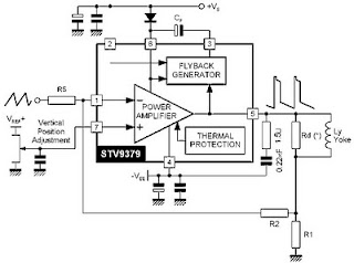
Various kinds of vertical out IC configuration.Ac coupling -connect from the yoke deflection output to a coil connected directly.Dc coupling - connected the output to the coil through a capacitor deflectioan yoke. Electrolityc Capacitors (usually worth 1000u/35v). This configuration requires two kinds of voltage (the voltage mirror plus-minus).Dc input coupling using diffferential - uses 2 input from the driver IC.

Vertical IC Configuration AC Coupling

Vertical IC Configuration DC Coupling

Read More...

Wednesday, April 10, 2013

4 Minute Shower Timer

Gone are the days when we can afford to luxuriate under a hot shower for hours on end. Well, maybe the showers weren’t quite that long but most people are used to taking showers in the tens of minutes. It’s easy to lose track of time in the shower. And it does feel nice.

That’s a luxury that’s no longer economically nor ecologically sustainable. First of all, we’re short of water. In most areas of Australia the powers-that-be keep telling us if we don’t be good boys and girls and cut our water usage then we are going to run out.

(Those same powers [read politicians] that keep blaming us wasteful consumers don’t mention that for the most part water shortages are their fault, because they haven’t invested the necessary dollars in water infrastructure while population has steadily increased for much of the last half century. But let’s not get into that argument. At least not right now . . .)

Second, we’re short of electric power. The power that goes to heat the water is also in very short supply. Load shedding (ie, blackouts!) is becoming more and more common as supply authorities attempt to cut peak loads. Those same powers-that-be keep telling us that if we don’t reduce our consumption of power, it’s going to get worse. (Those same powers [read politicians] that keep blaming us wasteful consumers, etc etc etc . . .)

Putting aside all the scare-mongering that’s going on in political circles (my spell checker wanted to change that to circuses, which would be perhaps more apt) it really does make sense for us, as consumers, to try to save both water and power – if only because that means less of our hard-earned dollars will end up in Government coffers.

One way to do both, of course, is to take shorter showers. How short?

The 4-minute shower

Believe it or not, it is entirely possible to take a shower in four minutes – including, if you need to, washing your hair. In fact, without shampooing, a sub-three-minute shower is perfectly practical. People in the bush who don’t have the luxury of hot water have been "getting" that sort of shower for years: get in, get wet, get clean, get out!

Let’s face it – all you really need to do is get wet, soap up and rinse off. Get wet: 30 seconds. Soap up: 60 seconds. Rinse off: 60 seconds. That’s two and a half minutes. Add another 60 seconds to shampoo your hair and there’s your four minute shower – with 30 seconds left over for good measure.

OK, if you agree that four minutes is enough time, how do you go about convincing everyone in your family?

4-minute-shower-timer-circuits-diagrams 1

The ST4 Shower Timer

This rather ingenious (and patented) design is completely automatic, turning on about 20-30 seconds after it "hears" the first "sssshhh" of the shower – giving you enough time to adjust the water temperature – then beeping each minute up to the magic four minutes, at which time it sounds an alarm.

The alarm stops when you turn the shower off. But if you try to fool it by turning the shower off for a moment and then back on again, the alarm will start back up again. It resets after about a minute of no-shower-sound, ready for the next person to take their shower.

Part of the secret to this circuit is the use of the piezo buzzer: it is not only sounds the beep/alarm, as you would expect but it is also used as a "microphone" to pick up the splash sound.

There’s no on-off switch; it simply operates when it hears the shower turn on (listening for the distinctive splashing sounds of the water). There is an internal 3-position switch and preset pot which are adjusted to give the desired sensitivity – once set, you can forget it.

There are also pots to control clock frequency and tone of alarm – but these are set in the factory and should not need touching.

It’s operated by a 9V battery (alkaline preferred) which should last for at least 12 months. Current drain, when ready to operate but inactive, is comparable to that of a smoke detector – around 10-15mA.

The circuit, including the piezo, is housed on a single PC board which fits (along with the 9V battery) into a purpose-designed two-part case. When correctly assembled is quite waterproof. Mounted on the shower wall it allows shower sound to enter and beeps/alarm to escape without the circuit getting at all damp.

The case, as we said, is in two parts. These snap together to form a nice, tight seal around the PC board, with alignment of the two parts taken care of by pins and holes which mate. Each half of the case is fitted with a suction cap which allows the unit to mount to any smooth shower wall (or even a glass screen).

While the ST4 Shower Timer is available fully built and tested, we are more interested in it as a kit which you assemble yourself. Even here, most of the hard work – soldering the surface-mount components and ICs – is already done for you. In fact, as supplied, the PC board is built and tested, ready for you to put together

Putting it together

Assembly is as simple as removing the backing and the centre from the self-adhesive "donut" foam ring and sticking it, as central as possible, onto the piezo transducer. Then similarly stick the rectangular foam pad onto the back of the PC board (it keeps the battery snug while preventing it shorting to or across the board), then push the PC board into the bottom half of the case.
4-minute-shower-timer-circuits-diagrams1

The bottom half can be identified by the slots for the transducer. When the board is pushed fully home, the foam donut "gasket" provides a seal in a moulded housing inside the case, preventing any water entering the case – theoretically even if dunked.

We say theoretically because it is designed that way – but commonsense would suggest you don’t try to prove it. Because the transducer slots are at the bottom of the case, spray would have to be travelling upwards to enter – possible, of course.

But the foam donut stops this water going any further. While the transducer itself is not sealed, its internal construction means that it is also an effective water barrier, so with the sealing donut in place, spray cannot enter the case nor either around or through the transducer.

All this means that the shower timer is for all intents and purposes waterproof, especially from spray. Once the PC board has been pushed home, the battery can be connected and slid down into the case, alongside the (now insulated) back of the PC board. It should be a relatively snug fit.

In the unlikely event that the suction caps have come off the case halves in transit, simply slide them back into their respective slots on each end – the photos show where they go. Slide the two halves of the case together, ensuring that the channels which hold the suction caps line up exactly – the pins in one half won’t mate if they don’t. The two case halves should "snap" together and that completes construction.

Testing

If you don’t want to get wet, you can use a small unmuted FM radio, off-station, to simulate the sound of a shower. (If your FM radio mutes automatically, or the mute cannot be turned off, this option won’t work. You’ll need to check it in situ – in the shower!) The FM radio will produce predominantly white noise, which is fairly close to the sound of a shower stream striking the bottom of the shower or bath.

Turn the radio on and the timer should give a chirping sound after 20-30 seconds (that’s the water temperature adjustment period). Then it should beep after each minute from there, with a series of beeps (7.5 seconds on, 7.5 seconds off) at the end of four minutes. Turn the radio off and the timer should reset.

Mounting in the shower

The timer always mounts vertically, with the piezo transducer towards the bottom. The suction caps should stick very well to any ceramic tile, glass or other smooth surface – if necessary, give ’em a lick first! Best position for the timer is about 300-400mm from the floor but it should work reasonably well up to about waist height.

If you need to mount the unit higher than this, or if it doesn’t appear to be sensitive enough, open it up and slide the switch up one notch. Don’t mount any higher than necessary. In some very low volume showers, (eg some gravity feeds), you might need to adjust the sensitivity right up but this would normally be unlikely.

You should not need to adjust any of the pots – they are preset on factory assembly. Once mounted, give it another run, this time with the shower. It should perform in the same way as it did in your "white noise" test.

The only time you should need to remove the unit from the wall is to replace the battery and this could be up to a couple of years or so! Don’t pull on the timer to remove it, slide a knife or some other thin, flat object under the suction caps to break the seal.

Read More...

Reservoir Pump Controller

This circuit operates an automotive windscreen washer pump to fill a 20-litre drum from a 205-litre water reservoir. The drum is suspended above a drip line, which irrigates a vegetable garden. Two stainless steel probes mounted in the drum act as sensors for the system. One probe is positioned at the high water mark, the other at about half-full. The pump power is switched by a 12V automotive relay (RLY1). Two op amps (IC1a & IC1b) connected as voltage comparators form the basis of the circuit. 

Initially, assume a falling water level with the pump switched off. When the water level exposes the lower probe, the non-inverting input (pin 5) of IC1b rises to about 7.4V. With trimpot VR2 correctly adjusted, this will be higher than the voltage on pin 6. The output (pin 7) therefore swings high, biasing Q1 into conduction. This in turn causes Q4 to conduct, switching on the relay and starting the pump. 

In addition, when Q4 switches on it supplies base current to Q3 via a 6.8kO resistor. Initially, this current flows through the 47µF capacitor, but once its base-emitter voltage reaches about 0.6V, Q3 conducts. This action latches Q4 in the "on" state, as its base current can flow to ground via Q3 when Q1 stops conducting – which will occur when the rising water level reaches the low probe. When the water level reaches the high probe, the voltage on the non-inverting input (pin 2) of IC1a decreases markedly due to the conductivity of the water.

Circuit diagram:
Reservoir-pump-controller circuit diagram
Reservoir Pump Controller Circuit Diagram

If trimpot VR1 is correctly adjusted, the output (pin 1) swings high, switching on Q2. This discharges the 47µF capacitor and robs Q3 of its base current, switching this transistor off. This in turn switches off Q4 and the relay. The zener diodes and 1kO series resistors at the probe inputs protect the op amp’s high impedance inputs from the effects of static discharge. The 47µF capacitor in parallel with the base-emitter junction of Q1 prevents the latching function from being activated when power is applied to the circuit. The author’s setup is powered from an old car battery charged from a 12V solar panel.
 
 
Source by : Streampowers
Read More...

1957 58 Dodge 4 Way Power Seat Wiring Diagram

1957-58 Dodge 4-Way Power Seat Wiring Diagram
(click for full size image)

The Part of 1957-58 Dodge 4-Way Power Seat Wiring Diagram:4 way seat adjusting switch, 30 amp circuit breaker, horizontal adjusting unit, battery,
Read More...

LED Christmas Star

This circuit can be used to construct an attractive Christmas Star. When we switch on this circuit, the brightness of lamp L1 gradually increases. When it reaches the maximum brightness level, the brightness starts decreasing gradually. And when it reaches the minimum brightness level, it again increases automatically. This cycle repeats. The increase and decrease of brightness of bulb L1 depends on the charging and discharging of capacitor C3. When the output of IC1 is high, capacitor C3 starts discharging and consequently the brightness of lamp L1 decreases. IC2 is an opto-isolator whereas IC1 is configured as an astable multivibrator. The frequency of IC1 can be changed by varying the value of resistor R2 or the value of capacitor C1.

LED Christmas Star
Remember that when you vary the frequency of IC1, you should also vary the values of resistors R3 and R4 correspondingly for better performance. The minimum brightness level of lamp L1 can be changed by adjusting potentiometer VR1. If the brightness of the lamp L1 does not reach a reasonable brightness level, or if the lamp seems to remain in maximum brightness level (watch for a minute), increase the in-circuit resistance of potmeter VR1. If in-circuit resistance of potmeter VR1 is too high, the lamp may flicker in its minimum brightness region, or the lamp may remain in off state for a long time. In such cases, decrease the resistance of potmeter VR1 till the brightness of lamp L1 smoothly increases and decreases. When supply voltage varies, you have to adjust potmeter VR1 as stated above, for proper performance of the circuit. A triac such as BT136 can be used in place of the SCR in this circuit. Caution: While adjusting potmeter VR1, care should be taken to avoid electrical shock.
 
 
sourrce
Read More...